From the View | Toolbars
| Graphics Modes toolbar, click the CAD
Lighting icon  .
.
From the Edit menu, point to Graphic Display Window, and choose Lighting, Materials.
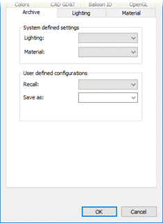
The CAD and Graphic Setup dialog box gives you a set of tools that allows you to further manipulate the display of CAD models (such as your part model) inside the Graphic Display window. These models include your part model, probe model, machine model, and other fixture models.
You can also use the dialog box to change other properties that affect how things are drawn on the screen.
You can open the dialog box by doing one of the following:
From the View | Toolbars
| Graphics Modes toolbar, click the CAD
Lighting icon  .
.
From the Edit menu, point to Graphic Display Window, and choose Lighting, Materials.

CAD and Graphic Setup dialog box
This dialog box contains these tabs:
Archive - This tab saves and recall these CAD configurations for later use.
Lighting - This tab defines and enables light sources, their colors, their directions, light models, and CAD transparency.
Material - This tab applies texture mapping to the surfaces of your CAD models. You can also change the colors and brightness of the materials making up the textures.
Clip Planes - This tab defines up to four Clipping Planes that hide your part model in the clipped area. You can use this feature to cut your part model to show cross sections and cutaway views.
Trihedron - This tab modifies the main alignment trihedron's size as well as the color of each axis and component of the trihedron symbol.
Symbols - This tab sets the properties for the display of the following:
Wireframe and surface objects
Point symbols
Path lines
Wireframe - This tab defines the color and width of surface edges.
Colors - This tab defines the colors for the following:
The screen's background color
The highlight color
The mouse-over highlight color
The 3D grid color
The Vision's Field of View (FOV) color.
CAD GD&T - This tab defines the colors and other options for CAD GD&T callouts.
Pan, Zoom, Rotate - This tab defines how PC-DMIS interprets mouse gestures for pan, zoom, and rotate in the Graphics Display window.
Balloon ID - This tab uses a Microsoft Excel file to map characteristic IDs to balloon numbers.
OpenGL - This tab defines the OpenGL options that affect the display of the model in solid view mode.
These four buttons are at the bottom of the dialog box:
OK - Accepts your changes and closes the dialog box.
Cancel - Rejects your changes and closes the dialog box.
Save System Defaults - Saves your changes as the new default lighting and material settings. This overwrites the default settings that came with PC-DMIS.
Restore System Defaults - This brings back the original lighting and material settings that came with PC-DMIS.
Any modifications you make to the CAD and Graphic Setup dialog box take place in real time in the Graphic Display window. This lets you immediately see the effects of your selected changes. Until you click OK, however, the changes you make are only temporary.
Settings to appropriately display CAD models
PC-DMIS renders CAD models best when the CAD geometry, including the surface features, is set to transparent. This is accomplished by selecting the Enable transparency check box on the Lighting tab of the CAD and Graphics Setup dialog box.
If the transparent CAD model needs to be more visible, lower the transparency:
Access the CAD and Graphic Setup dialog box (Edit | Graphic Display Window | Lighting, Materials).
From the Lighting tab, set the Transparency slider to a lower value, such as 50%.
To produce a better and more accurate rendering of your model:
From the CAD and Graphic Setup dialog box, click the OpenGL tab.
From the OpenGL tab, select the High quality transparency check box.
From the Lighting tab, select the Single layer check box.
Set the Transparency slider as needed, such as 70%.
More: