
CAD Model Views dialog box
A single CAD model view (previously known as a "CAD capture") consists of one or more selected CAD elements stored in that view. Similar to CAD Groups, you can use the CAD Model Views dialog box (Edit | Graphic Display Window | CAD Model Views) to define multiple CAD model views and what CAD to store in each view. You can also activate or deactivate the CAD views to show or hide the stored CAD elements within it. It essentially controls the visibility of CAD elements. However, it does more than CAD Groups, because the dialog box can also control the following:
Visibility of CAD elements
Visibility of CAD assembly components
Optional view orientation
Optional scale-to-fit operation
Optional rendering mode (shaded/wireframe, surface edges on/off)
Optional clipping plane
Many CAD systems provide the ability to add views directly into the CAD model. When you import those models, you can access those views from the CAD Model Views dialog box.
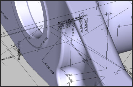
Portion of a CATIA Model Showing CAD Model Views (the GD&T or other text-like CAD elements)
Creating CAD Views from the CAD Models View Dialog Box
This procedure assumes you haven't created any views yet.
Click Create to add New Model View 1 into the list of views.
From the list, select New Model View 1.
From the Graphic Display window, ensure you have a visible part model.
You can use the Editing area to mark or clear the check boxes. These control whether or not the software saves the view orientation, scale to fit, shading, and clipping plane into the selected view.
From the part model, click on one or more CAD elements to highlight them.
Click Add to add the selected CAD elements to the selected view.
If you want to rename the view to something else to better reflect its the stored CAD elements, click Rename and type a new name.
Continue creating CAD model views as needed. The next time you click Create, the software increments the number in the newly added view (for example, New Model 2).
Activating CAD Views from the CAD Model Views Dialog Box
From the list of created views, double-click on a CAD view to activate that view. When you activate a view, the software does the following:
It highlights the view in the list and shows CAD elements that are in the activated view in the Graphic Display window.
It updates the visible CAD assembly components to the state stored in the view.
Based on the selected options, it can change the view orientation, perform a scale-to-fit operation, change the shading, and enable a clipping plane.
It temporarily hides all other CAD elements and CAD assembly components.
You can also activate a CAD view from the list on the CAD Setup toolbar. For information, see the "CAD Setup Toolbar" topic in the "Using Toolbars" chapter.
About the CAD Model Views Dialog Box
List - The list shows all the views in the CAD model.
To activate a view, double-click on the view in the list. The activated
view has a bold font face. To deactivate a view, double-click on the activated
item in the list. If a CAD model view contains embedded CAD GD&T
callouts, this icon ( ) appears next to that item in
the list. For information on CAD GD&T callouts, see the "Working
with CAD GD&T Callouts" topic.
) appears next to that item in
the list. For information on CAD GD&T callouts, see the "Working
with CAD GD&T Callouts" topic.
Create - This button creates a new CAD model view and adds any visible CAD GD&T elements into it.
Rename - This button renames the selected view name.
Delete - This button deletes the selected view. It does not delete any CAD elements.
Add - This button adds selected CAD elements to the selected view.
Subtract - This button removes the currently selected CAD elements from the selected view. It does not delete any CAD objects.
Select - This button selects all CAD elements contained in the selected view.
Deselect All - This button deselects all selected CAD objects.
Selection filter - The check boxes in this area filter selected CAD elements when you box-select them so that the software only selects the selected object types.
View orientation - If marked, this check box stores the current view orientation into the selected view. If cleared, and you activate the model view, the orientation view does not change. If you change the orientation and then mark this check box again, it uses the new orientation.
Scale to fit - If marked, this check box performs a scale-to-fit operation when you activate the view.
Shading - If marked, this check box stores the current shading (solid or wireframe) and the current surface edges state (on or off) into the selected view. When you later activate the view, it uses the stored shading regardless of the current Graphic Display window's shading. If you clear this check box and you activate the view, the shading uses whatever the Graphic Display window uses. To change the stored shading state, you can clear and mark this check box again to tell the view to use the current Graphic Display window shading.
Clipping plane - If marked, this check box stores the current clipping plane into the selected view. If you import a model that has a clipping plane defined in its view, that clipping plane temporarily exists in the model for that view. If you then clear the Clipping plane check box, the clipping plane is permanently removed. This check box remains disabled until you define a clipping plane. For information on creating and using a clipping plane, see the "Clip Planes Tab" topic.
Update from assembly - This button updates the selected view with the assembly view defined in the CAD Assembly dialog box. For information on manipulating the assembly view in that dialog box see, "Working with Assemblies of Parts".