 to open the CAD
Groups dialog box.
to open the CAD
Groups dialog box.Similar to a CAD level, a CAD group consists of a group of user-selected CAD geometries called "elements" selected from the Graphic Display window.
However, CAD groups differ from CAD levels in these respects:
CAD elements can belong to more than one CAD group and there can be any number of these groups.
CAD elements in a CAD group can span CAD levels.
CAD elements in a CAD group can span across multiple assembly components.
A CAD group's settings apply to all views of the graphical model.
Select Edit | Graphic Display Window
| CAD Groups or from the Graphics Modes
toolbar, click the CAD Groups button  to open the CAD
Groups dialog box.

CAD Groups dialog box
This dialog box lets you define the CAD elements that are assigned to the groups. You can also use the dialog box to modify groups, delete groups, and view or hide groups in the Graphic Display window.
CAD group information is saved with the .CAD file, so that if you import the .CAD into another measurement routine, the group information is available there too.
The CAD Groups dialog box contains these items:
CAD Groups

The list of CAD groups in the upper-left area of the dialog box shows all the current CAD groups in the CAD model. Because CAD elements can be assigned to more than one group, this list lets you select (highlight) more than one group from the list at a time. So, for example, you could select a surface, then select two groups, and add that surface to both groups.
Here are some operations you can perform using this groups list:
Double-click on a group from the list to select all CAD elements assigned to that group.
Select a CAD element in the Graphic Display window and press and hold Ctrl on the keyboard to select the corresponding group in the group list.
Mark the check box next to a group to show the CAD elements assigned to it.
Clear the check box next to a group to hide the CAD elements assigned to it.
Visibility

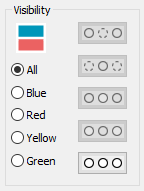
The Visibility area provides option buttons and icon buttons that allow you to run visibility operations in order to change the hidden state of the CAD groups. If a CAD object belongs to more than one group, and at least one of the groups is hidden, that CAD object becomes hidden as well. So, even if the CAD object is visible in another group, it is still hidden.
 The colored
icon at the top of this area shows your current screen layout. It corresponds
with the icon used in the Layout area of the
View Setup dialog box. See "Setting
Up the Screen View".
The Blue, Red, Yellow, and Green options limit the visibility operation to only that "view" of the Graphic Display window. The All option applies the visibility operation to all views.
These command buttons have pictures on them that depict their action:
 Hide - Hides the CAD group
selected in the list.
 Hide Siblings -
Hides all the CAD groups except the group selected in the list.
 Show - Shows the CAD group
selected in the list.
 Show Siblings -
Shows all the CAD groups except the group selected in the list.
 Show All - Shows
all the CAD groups in the list.
These buttons have a dark gray background and are unavailable for selection until you select a CAD group from the list of groups.
Editing

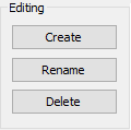
The Editing area allows you to modify CAD groups. For all buttons except Create, you need to first select at least one group from the CAD groups list, and the buttons affect the selected group or groups.
Create - Creates a new group. Initially, there are not any CAD elements assigned with this new group. You need to select the CAD elements from the Graphic Display window and then use the Add button in the CAD Elements section to add the selected CAD elements to the new group.
Rename - Renames the selected group. You can also rename a group by clicking on a selected group in the list until the cursor appears.
Delete - Deletes the selected groups (but not the CAD elements in those groups).
No Transform or Color buttons are used with CAD groups, because the CAD elements can belong to more than one group.
Saved Views

The Saved Views area stores the CAD group visibility state in the CAD model. These are saved inside the .CAD file. Use the drop-down combo box to either select or recall a saved visibility state, or to specify a name for a new view.
This CAD group visibility state does not include the number of graphics views. The number of graphics views can only be saved using viewsets. See "Working with Viewsets".
Save - Saves the current visibility state using the name entered in the combo box.
Delete - Deletes the saved visibility state selected in the combo box.
CAD Elements

The CAD Elements area modifies the group using the selected CAD elements. You can select multiple CAD elements by pressing Ctrl and clicking on them or by box-selecting them in the Graphic Display window. Selected elements are highlighted.
Add - Adds the selected CAD elements to the currently selected groups in the list.
Subtract- Removes the selected CAD elements from the currently selected groups in the list. If a selected CAD element is not on the selected group, then that CAD element is not modified.
Deselect All - Clears any selected CAD elements on the Graphic Display window.
Selection Filter - The check boxes in the Selection Filter area filter the type of CAD elements assigned to a CAD group. You can also use the Color check box in this area to filter selection by the color of the CAD element. When you select the Color check-box, the color of the next CAD element that you select in the Graphic Display window are used as the filter color. For subsequent selections, you can only select CAD elements with that color.
Creating CAD Groups
Access the CAD Groups dialog box.
Click Create from the Editing area. A new group appears with "New Group" as the default name followed by a unique number.
Select the group and rename it if desired by clicking again on the group or using the Rename button.
Ensure that the CAD group is selected from the list.
From the Graphic Display window, select the CAD elements you want included in the CAD group. Your selection can span multiple part models as part of an assembly or multiple layers. To limit which CAD element types are selectable, select the check boxes of CAD elements in the Selection Filter area.
Click the Add button. PC-DMIS assigns the selected elements to the selected group. Now when you show that group and hide other groups, PC-DMIS show only those elements.
Click OK when finished to close the dialog box.
Modifying CAD Groups
Access the CAD Groups dialog box.
Select the group from the CAD Groups list.
To add elements to the group, select the CAD elements from the Graphic Display window and click Add. PC-DMIS modifies the group accordingly.
To remove elements from the group, select the group and display its assigned CAD elements. From the Graphic Display window, select the elements to remove and click Subtract. PC-DMIS modifies the group accordingly.
Click OK when finished to close the dialog box.
Deleting CAD Groups
Access the CAD Groups dialog box.
Select a group from the CAD Groups list.
Click Delete.
Click OK when finished to close the dialog box.