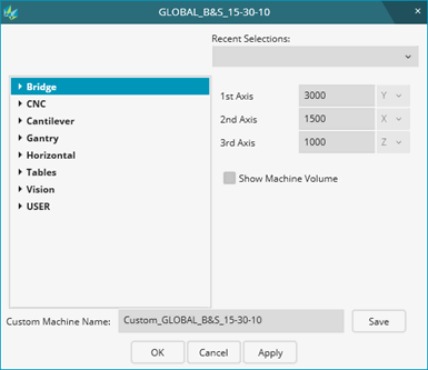
The Insert | Hardware Definition | Machine menu option displays the Load Virtual Machine dialog box.

Load Virtual Machine dialog box
With this dialog box, you can select or create a virtual measuring machine or virtual table that is displayed and animated in the Graphic Display window along with the probe and part model.

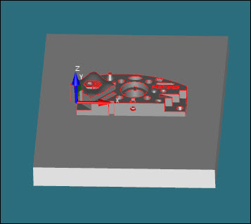
A sample virtual machine
If you import both a part model and a machine model into the Graphic Display window, and you don't have any outstanding manual machine offsets or rotations, PC-DMIS automatically positions the part model to the machine model's table.
If you have manual x,y,z, offsets or rotations from the Part/Machine tab of the Setup Options dialog box, you need to use that tab's Auto Position button to position the part model to the machine table. For more information on the Auto Position button, see the "Part Setup area" topic in the "Setting Your Preferences: Introduction" chapter.
You may not want to show a full virtual machine and instead may only want to display a virtual table (or CMM baseplate). You can do this by choosing an option from the Tables category from the list of machines.

A sample virtual table
The virtual table comes from a list of tables defined in the tablesonly.dat file. You can modify the .dat file to contain tables that match what you need.
More:
About the Load Virtual Machine Dialog Box
Selecting or Creating a New Animated Machine for Display
Displaying Existing Animated Machines in the Graphic Display Window
Removing the Animated Machine from the Graphic Display Window
Permanently Deleting an Animated Machine