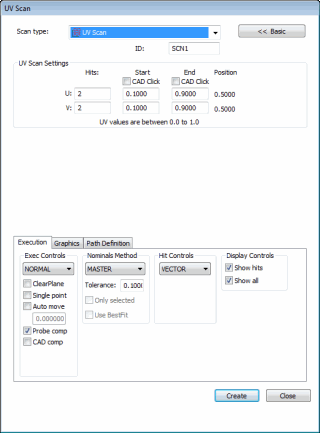

UV Scan dialog box
The Insert | Scan | UV scan enables you to easily scan rows of points on any surface of a known CAD model (similar to the Patch scan). This scan doesn't require a lot of setup because it uses the UV space as defined by the CAD model.

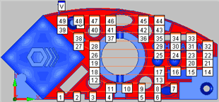
Example UV scan with each hit labeled
When PC-DMIS sets up the UV scan using this dialog box, it gets each of the points from the CAD and uses the nominal data for each point.
To Create a UV Scan
Enable a TTP probe.
Place your CAD model in Solid mode.
Place PC-DMIS into DCC mode.
Access the UV Scan dialog box (Insert | Scan | UV).
Type the name of the scan in the ID box if you want to use a custom name.
On the Graphics tab, click the Select check box.
Click the surface to scan. PC-DMIS highlights the selected surface. PC-DMIS displays a U and V on the CAD model, which indicate the direction of each axis.
On the Graphics tab, clear the Select check box.
Select the Start CAD Click check box in the UV Scan Settings area.
Click once on the selected surface to set the scan's start point. Where you click on the surface also indicates where the UV scan starts. This defines the first corner for the rectangular area for the scan.
The UV scan now supports scanning of multiple surfaces. To scan multiple surfaces, click on the surfaces to be scanned in the order you want them scanned. PC-DMIS displays a number indicating the surface number and the U and V direction arrows. During execution, PC-DMIS executes the UV scan on the first surface, then the second surface, and so on.
Select the End CAD Click check box in the UV Scan Settings area.
Click again on the selected surface to set the scan's end point. Again, PC-DMIS displays a U and V on the CAD model. This defines the second rectangular area for the scan.
PC-DMIS automatically determines the start and end positions along both the U and V axes based on the points you clicked. You can change the scan direction by switching the Start and End values in the U and V rows. UV space uses numbers between 0.0 and 1.0 to represent the entire surface. So in most cases, 0.0, 0.0 is the opposite diagonal corner from 1.0, 1.0. Trimmed surfaces, however, may start with a value greater than 0.0 and end with one less than 1.0 in both the U and V directions.
Select the appropriate type of hits to take from the Hit Type list in the Hit Controls area. You can select either Vector or Surface.
Modify any other options as needed.
Select the Generate button in the Theoretical Path area on the Path Definition tab to generate a preview of the scan on the CAD model in the Graphic Display window. PC-DMIS draws on the CAD model where the points should be taken. Notice that the UV scan automatically skips any impeding holes along the surface.
If needed, you can delete individual points. To do this, select them one at a time from the Theoretical Path area and press the Delete key.
Make additional modifications to your scan as needed.
Click the Create button. PC-DMIS inserts the scan into the Edit window and draws the route the probe will take on the surface of the model in the Graphic Display window.