Alignment Utilities dialog box
When you select Insert | Alignment | New (or press F9 on an existing alignment command), PC-DMIS displays the Alignment Utilities dialog box. This dialog box provides a way for you to construct an alignment from the features that have been measured up to that point in the measurement routine.
An alignment is not complete until you select the OK button and PC-DMIS updates the Active Alignment List box.
As long as the Alignment Utilities dialog box remains open, PC-DMIS indicates any remaining unconstrained degrees of freedom by causing the XYZ origin symbol (or alignment trihedron) to continually rotate about and translate in the direction of those unconstrained axes in the Graphic Display window. Once the alignment is completely constrained, PC-DMIS then displays the trihedron in a fixed location and orientation that represent the alignment position:

Alignment trihedron
ID box
This box defines the identification for the current alignment. If you are creating a new alignment, the alignment ID will default to a new name. To change the ID, type a new value in this box and press TAB.
Recall list
The Recall list contains all the internal alignments that have been defined in the measurement routine prior to this alignment. The alignment selected from this Recall list acts as the start condition of the current alignment.
If you are creating a new alignment, the Recall list will display the alignment active at the cursor's current location in the Edit window. If you have not defined any alignment, or if the cursor location is before any defined alignments in the Edit window, the STARTUP command is selected as the recalled alignment.
You can recall any available alignment listed in the Recall list. Only alignments created prior to the current cursor's position and certain predefined special cases are available for selection from that list.
Alignment Sub-Command list
This list displays a summary of each of the sub-commands that make up the current alignment block. This summary includes information such as the type of alignment sub-command, axis direction, and feature or features used by the sub-command to perform its rotation and/or translation.
Delete

The Delete button deletes the currently-selected sub-command from the Alignment Sub-Command list.
Best Fit

The Best Fit button opens the Best Fit dialog box. Use this dialog box to create or edit Best Fit alignments. See the "Creating a Best Fit Alignment" topic.
Iterative

The Iterative button opens the Iterative Alignment dialog box. Use this dialog box to create and edit Iterative alignments. See the "Creating an Iterative Alignment" topic.
Available features list
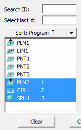
The Available features area displays all the available features in your measurement routine that exist above the current cursor location. These are the features available to your current alignment command.
You can also use the Graphical Hit Selection method to select inputs to your alignment. For details, see "Graphical Hit Selection Method".
For a full description, see "Feature List box" under "Dialog Box Description" in the "Navigating the User Interface" chapter.
The Search ID filters the list of features by the specified ID. Type the ID string, and press TAB.
The Select last # box-selects the final 'N' features in the list, where 'N' is the number you type. Type the number of features to select, and press TAB.
The Clear button clears the current feature selections from the list.

The Level area establishes the orientation of the normal axis of the current workplane.
To choose a feature to "level" to:
Select the feature to be used from the Feature List box.
Choose the axis to level to from drop-down list.
Click the Level button.

The Rotate area rotates the alignment to be parallel to a selected feature by a specific manual offset angle or by an angle defined from a picked CAD surface or edge.
PC-DMIS rotates the Rotate to axis around the alignment origin, about the specified alignment axis (About axis). The Rotate to and About axes cannot be the same axis.
The available options are:
ZPLUS
XPLUS
YPLUS
ZMINUS
XMINUS
YMINUS
Rotate to a Line between Two Circles
Rotate by a Manual Offset Angle
Rotate by a Picked CAD Surface or Edge

The Origin area moves the alignment origin to a specific feature location, by a specific manual offset distance, or by a distance defined from a picked CAD surface or Edge.
Move by a Manual Offset Distance
Move by a Picked CAD Surface or Edge
Auto-Set Origin for Level/Rotate
Auto-align

The Auto-align button uses the currently-selected features to automatically create the alignment sub-commands. The Auto-align button is active only when exactly one, two, or three features are selected from the list of available features, and there are no sub-commands currently defined for the alignment. Auto-align uses the same algorithms as QuickAlign. Auto-align supports all valid combinations of features selected.
For more information on QuickAlign, see "About QuickAlign".
CAD = Part

The CAD = Part (CAD Equals Part) button moves and orients the part origin defined by the alignment so that it is equal to the CAD origin. This option should be used after a created alignment places the part origin and orientation at the same location as the CAD origin and orientation. This can make it simpler to use the CAD data to help inspect the part by displaying the measured data directly on top of the CAD data.
To set the CAD equal to the part:
Measure features on the part or fixture.
Use the alignment options to create an alignment.
Select the CAD = Part button. After the CAD = Part button is selected for a part, the Operation | Graphic Display Window | CAD Equals Part menu item will be selected.
The CAD = Part button is only available if the alignment is at the very end of the measurement routine. If there are other commands after the alignment, PC-DMIS hides the button.
 .
.