In this Topic Hide
An angularity specification controls how much the feature can deviate from a specified angle to a datum. Sometimes you can use a secondary datum to control the tolerance zone's orientation.
For this geometric tolerance, these three aspects work together:
Each considered feature and each resulting toleranced feature
Each tolerance zone
The datum features
To evaluate this tolerance, PC-DMIS converts each considered feature to a toleranced feature. You can find this described in "Deriving the Toleranced Feature”.
PC-DMIS then optimizes each toleranced feature into its respective tolerance zone. The optimization process respects whatever constraints each datum imposes.
Each toleranced feature is optimized independently.
You can use these feature types:
cylinders, cones, planes, lines, 3D widths, and 2D widths
Some feature types have a different toleranced feature than the considered feature's surface data. These include 3D constructed BF lines, cylinders, cones, 3D widths, 2D widths, and planes with a tangent plane modifier. For more information, see "Deriving the Toleranced Feature”.
When the considered feature has an axis, the tolerance
zone shape can be diametric (with the tolerance zone shape symbol  ) or planar (no tolerance zone shape symbol). These are
the axial considered features:
) or planar (no tolerance zone shape symbol). These are
the axial considered features:
Cylinder
Cone
Surfaceless axis
For information on the feature command types that correspond to these feature types, see "Feature Types With and Without Surface Data".
Here is an example of an angularity on a cylinder with a diametric tolerance zone:
Here is an example of an angularity on a cylinder with a planar tolerance zone:

Planar tolerance zones on axial considered features need a specified tolerance zone orientation. This is because the feature does not have enough information to orient the zone correctly. In these cases, the Zone Orientation button in the Geometric Tolerance dialog box becomes visible. For information on how to use this button to change the zone orientation, see "Zone Orientation" in the "Feature Control Frame Tab" topic.
If a tolerance controls the X component of the orientation, the tolerance zone surface normal vector should be X.
Actual
Value:
This is the size of the smallest tolerance zone that contains the actual
toleranced feature. The zone is nominally oriented to the actual datum
or datums.
Measured
Value:
This is the size of the smallest tolerance zone that contains the measured
toleranced feature. The zone is nominally oriented to the measured datum
or datums.
Suppose you had this angularity specification:

In the above specification, the actual value looks like this:

In the above image, the actual part surface uses the solid line, the actual datum uses the dashed line, and the smallest tolerance zone containing the actual toleranced feature is shown in the shaded area. The tolerance zone is exactly 15° to the actual datum.
Finally, the measured value (with DEFAULT datum math) looks like this:

In the above image, the measured tolerance zone is exactly 15° to the measured datum. In this case, the measured points were not measured densely enough, and so the measured value is smaller than the actual value.
The considered feature or features are specified at some nominal angle to the datum feature or features.
Because of this, all input features (considered and datum) must have the correct specified nominal values. This also ensures that the tolerance command correctly identifies the optimizable degrees of freedom.
For a planar zone on axial features, the datum reference frame must fully constrain the tolerance zone orientation. The planar tolerance zone’s surface normal must be perpendicular to each considered feature's axis vector.
In PC-DMIS version 2020.2 and later, you can no longer type in the nominal angle from the considered feature to the primary datum. Instead, you need to ensure that the features (considered and datum) have the correct nominal values.
In PC-DMIS version 2020.2 and later, material modifiers on datums are no longer allowed.
When the considered feature
is a cylinder or a width, angularity allows a maximum material modifier
 to indicate
the specification is at the maximum material condition (MMC). Alternatively,
it allows a least material modifier
to indicate
the specification is at the maximum material condition (MMC). Alternatively,
it allows a least material modifier  to indicate
the specification is at the least material condition (LMC). This means
that as the unrelated mating envelope size (or unrelated minimum material
envelope size for LMC) deviates from the MMC (or LMC), additional tolerance
or "bonus" tolerance is added to the tolerance in the feature
control frame, yielding a total tolerance. For more information on
this bonus tolerance, see "Evaluating
Size with the Geometric Tolerance Command".
to indicate
the specification is at the least material condition (LMC). This means
that as the unrelated mating envelope size (or unrelated minimum material
envelope size for LMC) deviates from the MMC (or LMC), additional tolerance
or "bonus" tolerance is added to the tolerance in the feature
control frame, yielding a total tolerance. For more information on
this bonus tolerance, see "Evaluating
Size with the Geometric Tolerance Command".
Suppose a cylindrical hole has an angularity tolerance 0.002 at MMC, as shown here:
The size tolerance is 0.675 plus or minus 0.025, meaning the range of acceptable sizes is 0.650 to 0.700. The maximum material condition is then 0.650. If the unrelated measured mating envelope size is 0.661, then the bonus tolerance is 0.011, and the total tolerance is 0.013.
When the considered feature
is an auto feature cylinder, you can use a projected-zone modifier  as shown here:

This projects (extrapolates) the measured feature axis as described in "Deriving the Toleranced Feature".
When the considered feature
is a plane with surface data, you can use a tangent-plane modifier  ,
as shown here:
,
as shown here:

This makes the toleranced feature be a perfect-form plane tangent to the actual surface, as described in "Deriving the Toleranced Feature".
When the considered feature has surface data, and the toleranced feature differs from the considered feature’s surface data (cones, cylinders, and widths), the feature math type controls how to compute the toleranced feature from the considered feature’s surface data. For information, see "Deriving the Toleranced Feature”.
When at least one datum feature has surface data, the datum math type controls how to compute the measured datums from the datum features' surface data. For more information, see "How PC-DMIS Solves Datums".
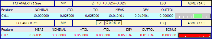
Here is an example report for an angularity tolerance. The cylinder's size tolerance is in the upper label, and the diametric-zone angularity is in the lower label.