
In this Topic Hide
How PC-DMIS Solves and Uses Datums
Degrees of Freedom Constrained by a Datum Reference Frame
Datum Math Types under ASME Y14.5
Datum Math Types under ISO 1101
Datum Planes with Surface Data under ASME Y14.5
Datum Planes with Surface Data under ISO 1101
Illustrations of Datum Planes: Filtration, Best Fitting, and Orientation Constraints
Datum Planes without Surface Data
Datum Cylinders with Surface Data under ASME Y14.5
Datum Cylinders with Surface Data under ISO 1101
Illustrations of Datum Cylinders: Location Constraints and No Location Constraints
Datum Cylinders without Surface Data, and Surfaceless Axes
Datum Cones with Surface Data under ASME Y14.5
Datum Cones with Surface Data under ISO 1101
Datum Cones without Surface Data
Datum Spheres with Surface Data under ASME Y14.5
Datum Spheres with Surface Data under ISO 1101
Datum Spheres without Surface Data, and Surfaceless 3D Points
Illustrations of Datum Patterns
Common Datums: Coaxial Cylinders
Illustrations of Coaxial Datums
Common Datums: Offset Parallel Planes
Datums with a Material Modifier
Illustrations of Datums with a Material Modifier
Determining the Size of the Material Boundary
Rules to Determine Geometric Tolerance
Secondary Datums Under ISO 1101
Tertiary Datums Under ISO 1101
Primary Datums Under ASME Y14.5
Secondary Datums Under ASME Y14.5
Tertiary Datums Under ASME Y14.5
Datums with Unconstrained Location Compared to Higher-Precedence Datums
Many geometric tolerances reference one or more datums. Datums serve to align the actual surfaces with the nominal geometry so that position, perpendicularity, runout, and other tolerances, can be evaluated with respect to those datums.
First, PC-DMIS best-fits all of the actual primary datum surfaces to their respective datum simulators.
Second, PC-DMIS best-fits the actual secondary datum surfaces to their datum simulators while preserving the relationship (interaction) between the actual primary datum surfaces and their datum simulators.
Third, PC-DMIS best-fits the actual tertiary datum surfaces to their datum simulators, while preserving the relationship (interaction) between the actual primary and secondary datum surfaces and their datum simulators.
Finally, all toleranced features are optimized into their tolerance zones, preserving the relationship (interaction) between the datum surfaces and their simulators.
This process is much like using a functional gage:
First, the part is brought to the gage and the actual primary datum surface is aligned to the gage's primary datum simulator.
Second, the actual secondary datum surface is aligned to the gage's secondary datum simulator, keeping the actual primary datum surface aligned to the gage's primary datum simulator.
Third, the actual tertiary datum surface is aligned to the gage's tertiary datum simulator, keeping the actual primary and secondary datum surfaces aligned.
Finally, the considered features are evaluated, using gage pins or something similar.
Terminology Note: There are several phrases used in the GDT standards to describe the concept of a datum simulator. ASME Y14.5 - 2009 uses "datum simulator." ASME Y14.5 - 2018 uses "true geometric counterpart." ISO 5459 uses "associated datum feature." These phrases are approximately equivalent. This document uses the phrase "datum simulator" for brevity.
There are two ways to think about the datum reference frame process, which are equivalent to each other.
The gage point of view.
The actual part can be aligned to the nominal geometry as described above. The nominal geometry (or gage) is fixed and the actual part is aligned to it.
The part point of view
The actual part is fixed and the nominal geometry (or gage) is aligned to it. Under the part point of view, PC-DMIS best-fits the datum simulators to the actual part. You can use either point of view to describe how geometric tolerances and datums are solved in PC-DMIS.
The remainder of this topic uses the part point of view to describe how PC-DMIS solves datums.
Comparison to Past Practice
Prior to PC-DMIS 2020.2, with the XactMeasure command, datum reference frames were handled rather like a PC-DMIS alignment, with a level feature, a rotate feature, and one or more origin features. All of these features you selected from the datum features. Starting with version 2020.2, the geometric tolerance command does not use any alignment concepts for datum reference frames. Instead, it uses gage concepts for the datum reference frames. This enables support for more unusual datum reference frames that cannot be represented by the level-rotate-origin framework.
A geometric tolerance without any datum references has no degrees of freedom constrained: all three degrees of translation and all three degrees of orientation are free. Each successive datum constrains more degrees of freedom. Specifically, after a datum has been solved, any translations and rotations are not allowed to alter the datum simulator. For example, after a primary datum plane is solved, the secondary and tertiary datums are not allowed to move the primary datum plane. That means translations within the primary datum plane are allowed, and rotations within the primary datum plane are allowed, but rotation or translation out of plane are not allowed.
These constraints are mathematically defined in terms of invariance classes. Each invariance class is defined below, with some examples of datums exhibiting the invariance class. The examples are not exhaustive: many more examples exist that are not listed.
Spherical invariance: the spherical invariance class constrains three translation degrees of freedom, and leaves unconstrained all 3 rotations about a center-point. This includes both spherical features and surfaceless 3D points.
Planar invariance: the planar invariance class constrains rotation about two directions orthogonal to the surface normal, and translation along the surface normal. It leaves unconstrained the rotation about the surface normal and translation along the two directions orthogonal to the surface normal. This includes planes, plane cross sections (lines on a surface) referenced as a secondary or tertiary datum, plane samples (points on a surface), and all width types.
Cylindrical invariance: the cylindrical invariance class constrains rotation about the two directions orthogonal to the axis vector, and translation along the two directions orthogonal to the axis vector. It leaves unconstrained the rotation about the axis, and translation along the axis. This includes cylinders, circles referenced as a secondary or tertiary datum, surfaceless axes, and conical surfaces which are treated as axis-only (see the subtopics on cones below).
Revolute invariance: the revolute invariance class constrains rotation about the two directions orthogonal to the axis vector, and all three translation degrees of freedom. It leaves unconstrained the rotation about the axis. This includes circles referenced as a primary datum (see "Datum Cylinder Cross Sections" below) and patterns of two non-concentric spheres.
Prismatic invariance: the prismatic invariance class constrains all three orientation degrees of freedom, and translation along two directions orthogonal to the translation vector. It leaves unconstrained translation along the translation vector. This includes plane cross sections (lines on a surface) referenced as a primary datum (see "Datum_Plane_Cross-Sections" below) and patterns of parallel non-coaxial cylinders.
Complex invariance: the complex invariance class constrains all degrees of freedom. This includes patterns of non-parallel cylinders and patterns of three non-coaxial spheres. Datum reference frames with complex invariance are often called fully-constrained datum reference frames.
When more than one datum is referenced, the invariance class of each datum must be combined so that none of the datum simulators are allowed to move.
Example 1: A primary datum
plane combined with a secondary datum circle in that plane yields a revolute
invariance class. The primary datum plane constrains three degrees of
freedom, and the secondary datum circle constrains two more degrees of
freedom (translation in the plane).
Example 2: A primary datum plane, a secondary
datum line on a surface, and a tertiary datum point on a surface yields
a complex invariance class. The primary datum constrains three degrees
of freedom yielding a planar invariance class. Adding the secondary datum
constrains two more degrees of freedom, yielding a prismatic invariance
class. Adding the tertiary datum constrains the remaining translation
degree of freedom, yielding a complex invariance class.
Example 3: A primary datum sphere combined with
a secondary datum sphere (not concentric with the primary) has a revolute
invariance class. The primary datum sphere constrains three degrees of
translation, and the secondary datum sphere constrains two degrees of
orientation. The line between the two spheres is the axis of the revolute
invariance class.
Comparison to Past Practice
Starting in PC-DMIS 2020.2, the geometric tolerance command analyzes the datum reference frame in terms of invariance classes. This enables correct handling of unusual datum reference frames where the vectors are not square to each other. For example, a primary datum plane with a secondary datum plane at a 30 degree angle to the primary has a prismatic invariance class. Prior to this version, PC-DMIS did not fully support these unusual datum reference frames.
As discussed in "Specification Versus Verification" in "Introduction to Geometric Tolerances and Feature Control Frames", we offer multiple math types for datum computation. PC-DMIS provides two ways to compute an ASME measured datum simulator using measured surface data. These are the two datum math types available:
DEFAULT - This does a void filtration (planar surfaces only) and a constrained least squares best fit. This algorithm is extremely similar to the actual simulator definition and so it is a good choice when the measurement uncertainty of each point is much less than the form error of the surface.
LSQ - This does a plain least squares best fit to the surface data. No void filtering is done. This algorithm is mathematically rather different than the actual simulator definition, but it is a better choice than DEFAULT when the measurement uncertainty of each point is much larger than the form error of the surface and much larger than the orientation error of the surface to higher precedence datums.
In between the two extremes, where the measurement uncertainty of each point is at least on the same order of magnitude as the form error, and at most on the order of magnitude as the orientation error, it can be difficult to predict which math type will yield a closer measured approximation to the actual datum simulator. The only way to be sure which type is the better choice is to do a careful study:
First, use a collection of manufactured parts that represent the range of manufacturing errors to control.
Second, measure the parts densely, using lots of cross sections. Use high-end equipment with much lower measurement uncertainty of each point than the form error. Compute the datums with the DEFAULT datum math type described above.
Finally, measure the parts with the actual equipment and measurement strategies used in production.
You can experiment with the two math types to see which one is closer to the high-accuracy result.
For any datum math option, we recommend that you measure the datum surface densely to maximize how well the measured datum simulator approximates the actual datum simulator.
As discussed in the "Specification Versus Verification" subtopic in "Introduction to Geometric Tolerances and Feature Control Frames", we offer multiple math types for datum computation. PC-DMIS provides three ways to compute an ISO measured datum simulator using measured data. These are the three datum math options available:
DEFAULT - This does a void filtration (all surface types) and a constrained min max, maximum inscribed, or minimum circumscribed best fit (depending on feature type, whether the surface is inner or outer, and the material modifier). This algorithm is extremely similar to the actual simulator definition, and so it is a good choice when the measurement uncertainty of each point is much less than the form error of the surface.
LSQ - This does a plain least squares best fit to the surface data. No void filtering is done. This algorithm is mathematically rather different than the actual simulator definition, but it is a better choice than DEFAULT when the measurement uncertainty of each point is much larger than the form error of the surface and much larger than the orientation error of the surface to higher precedence datums.
In between the two extremes, where the measurement uncertainty of each point is at least on the same order of magnitude as the form error, and at most on the order of magnitude as the orientation error, it can be difficult to predict which math type will yield a closer measured approximation to the actual datum simulator. The only way to be sure which type is the better choice is to do a careful study:
First, use a collection of manufactured parts that represent the range of manufacturing errors to control.
Second, measure the parts densely, using lots of cross sections. Use high-end equipment with much lower measurement uncertainty of each point than the form error. Compute the datums with the DEFAULT datum math type described above.
Finally, measure the parts with the actual equipment and measurement strategies used in production.
You can experiment with the two math types to see which one is closer to the high-accuracy result.
CL2 - This does a void filtration (all surface types) and a constrained least squares best fit. Like the DEFAULT datum math option, this option requires the measurement uncertainty of each surface point to be much less than the form error of the surface. This option deviates from ISO 5459 - 2011; reasons for doing so might include:
Stability: The constrained least squares algorithm gives a more stable result than constrained min max, maximum inscribed, or minimum circumscribed best fits.
Comparison to physical inspection methods: The constrained least squares algorithm is a closer approximation to a surface plate than constrained min max.
Comparison to assembly: The constrained least squares algorithm is a closer approximation to the assembled state than constrained min max.
Support future standards: The past several unpublished drafts of ISO 5459 have specified constrained least squares as the default and so it seems likely the next edition of ISO 5459 will do the same.
For any datum math option, we recommend that you measure the datum surface densely to maximize how well the measured datum simulator approximates the actual datum simulator.
For planes, the actual datum plane simulator is defined by ASME Y14.5.1 - 2019. The actual surface is filtered to remove dents and other voids, and then a perfect plane is fitted to the filtered surface using constrained least squares. This fit makes the simulator external to the material while it maximizes contact and stability. In cases where the actual surface would rock, the constrained least squares definition produces a stabilized solution.
Secondary and tertiary actual datum plane simulators are nominally constrained in orientation to higher-precedence datum simulators. Secondary and tertiary datum planes are not restricted in location compared to higher-precedence datum simulators. This means that a translation modifier on a datum plane is the same thing as no translation modifier.
When datum planes have surface data, PC-DMIS computes a measured approximation to the actual datum using that surface data and using the chosen datum math option. For details on planes that have surface data, refer to "Feature Types With and Without Surface Data".
For planes, the actual datum plane simulator is defined by ISO 5459 - 2011, using the phrase "associated datum feature." The actual surface is filtered to remove dents and other voids, and then a perfect plane is fitted to the filtered surface using constrained min max. This fit makes the simulator external to the material, with the low points of the filtered surface as close as possible to the actual datum simulator.
Secondary and tertiary actual datum plane simulators are nominally constrained in orientation to higher-precedence datum simulators. They are not restricted in location compared to higher-precedence datum simulators.
When datum planes have surface data, PC-DMIS computes a measured approximation to the actual datum using that surface data and using the chosen datum math option. For details on planes that have surface data, refer to "Feature Types With and Without Surface Data".
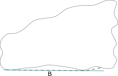
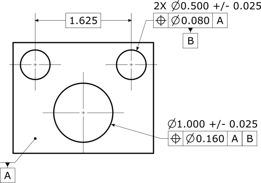
As an example of the best-fitting process, suppose you had the following specification:
It's easier to illustrate void filtering and best fitting in 2D than 3D, so let's suppose datum B was measured as a line instead of as a plane (even though we recommend that you measure it as a plane). The measured points might look like this:

Then the void-filtered surface would look like shown below in green:

Then the best-fitted constrained least squares line (the result of the DEFAULT datum math option for ASME, or the CL2 datum math option for ISO) is best fitted to the filtered surface, and looks like this shown in blue:
By contrast, the best-fitted constrained min max line (the result of the DEFAULT datum math option for ISO) is best-fitted to the filtered surface, and looks like this shown in blue:
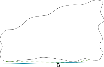
Meanwhile, the (unconstrained) least squares line (the result of the LSQ datum math option) is best-fitted to the original measured points, and looks like this shown in blue:

In this particular case, the DEFAULT datum math option is a better approximation to the actual datum than the LSQ datum math option. However, as seen in "Introduction to Geometric Tolerances and Feature Control Frames", the LSQ datum math option is a better approximation to the actual datum when the measurement uncertainty of each measured point is larger. Meanwhile, the CL2 math type under ISO gives a better approximation to the assembled behavior of the datum, but a poorer approximation to the actual (specified) datum.
As an example of orientation constraints, suppose you had the following specification:

Then the actual (specified) datums for a realistic part might look like this:
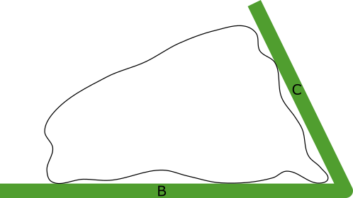
Note that actual datum simulator C has the nominal angle to actual datum simulator B. Also note that the datum simulator C contacts the actual surface in exactly one point.
In rare applications, a datum plane is defined that does not have a surface. For example, a plane that contacts three spheres. PC-DMIS supports applications like this by allowing for datum feature types that do not have surface data.
When a primary datum plane does not have surface data, the geometric tolerance command uses the MEAS values of the plane as the datum simulator.
When a secondary or tertiary datum plane does not have surface data, the geometric tolerance command uses the MEAS values of the plane as the datum simulator, re-oriented around its centroid so that they are nominally oriented to higher-precedence datum simulators. The re-orientation is done in a way that minimally rotates the datum. As seen above, ASME and ISO secondary and tertiary datum planes are not nominally located to higher-precedence datums, and so datum planes without surface data do not have their centroids moved.
As discussed in "Structuring your Measurement Routine for Geometric Tolerances", in most cases we do not recommend using datum planes without surface data, because you are taking over phases 2 and 3 of the conceptual evaluation process. If you do so, it is your responsibility to construct the feature according to appropriate standards.
For details on planes that do not have surface data, refer to "Feature Types With and Without Surface Data".
Datum line features can be either a cross section of a planar surface (see "Feature Types With and Without Surface Data") or a surfaceless axis. This subtopic here discusses the cross section case. The surfaceless axis is discussed in "Datum Cylinders without Surface Data, and Surfaceless Axes".
Because these types of line features represent a cross section of a planar surface, the above sections on datum planes apply here. For example, the actual datum simulator is an entire planar surface. By contrast, the measured datum simulator is a cross section of a planar surface because only a cross section of the surface was measured. This means we recommend that you do not use line features that represent a plane cross section as a primary datum. You should only use these line features as a datum if higher precedence datums have already defined the workplane of the line. However, PC-DMIS still allows these lines to be used as a primary datum. In that case PC-DMIS levels to the view of the line before it considers the datum line itself:
The view of a measured line or best-fit line is its workplane.
The view of an auto-line is its nominal surface vector.
Because lines are not recommended as a primary datum, PC-DMIS shows a warning message, as discussed in "Troubleshooting error messages and warnings". It may seem counter intuitive, but a primary datum line on a surface constrains five degrees of freedom (prismatic invariance class), while a primary datum plane constrains only three degrees of freedom (planar invariance class). This means if you measure less data, you are actually constraining more degrees of freedom. This is because you are requiring the line's view to become an implicit datum that is higher precedence than any datums in your feature control frame.
If you use a line on a surface as a primary datum, the warning cannot be turned off. This is because we strongly recommend that you do not use surface lines as primary datums. However, PC-DMIS supports this case for legacy applications. Instead, we recommend that you measure the datum plane first, and use that as the primary datum. Then measure a plane or line as the secondary datum.
Most line features referenced as a datum are on a surface—they have surface data. While it is possible in PC-DMIS to measure a line on a non-planar surface, the geometric tolerance command always handles lines on surfaces as coming from a planar surface. Because the measured datum simulator is only a cross section of the planar surface, the measured algorithms (void filtering and fitting) are all two-dimensional instead of three-dimensional.
We do not recommend that you use lines representing cross sections of planar surfaces for datum features unless you already know that the orientation error is very small between higher precedence datums and the planar surface represented by the line. Instead, we recommend that you use plane features to represent the secondary or tertiary planar surface whenever possible.
PC-DMIS handles datum lines that represent a planar cross section that do not have surface data somewhat like datum planes that do not have surface data. PC-DMIS minimally re-orients the measured surface normal about its centroid until it is nominally oriented to higher-precedence datum simulators. As discussed in "Structuring your Measurement Routine for Geometric Tolerances", in most cases we do not recommend using datum features without surface data, because you are taking over phases 2 and 3 of the conceptual evaluation process. If you do so, it is your responsibility to construct the feature according to appropriate standards.
The measured surface normal of a line is parallel to the cross product of its line vector and its workplane vector.
For details on lines that represent a plane cross section and that have surface data, refer to "Feature Types With and Without Surface Data"
The geometric tolerance command treats most point types as a single sample of a planar surface. While it is possible in PC-DMIS to measure a point on a non-planar surface, the geometric tolerance command always handles datum points on a surface as if they come from a planar surface. Therefore, the above sections on datum planes apply here. For example, the actual datum simulator is an entire planar surface. By contrast, the measured datum simulator is a single sample of a planar surface. This is because only a sample of the surface was measured. That means void filtering does not take place. The orientation of the planar surface must be completely constrained by higher-precedence datums (no fitting takes place). You can only use a sample of a planar surface as a tertiary datum.
We do not recommend that you use points on a surface for datum features unless you already know that the orientation error is very small between higher precedence datums and the planar surface represented by the point. Instead, we recommend that you use plane features to represent the tertiary planar surface whenever possible.
For details on the points that represent a sample of a planar surface, refer to "Feature Types With and Without Surface Data"
For cylinders, the actual datum simulator is defined by ASME Y14.5.1 - 2019. A perfect cylinder is fitted to the actual surface using constrained least squares.
There is no void filtration. This fit makes the simulator external to the material while it maximizes contact and stability. In cases where the actual surface would rock, the constrained least squares definition produces a stabilized solution.
Secondary and tertiary actual datum cylinder simulators are nominally constrained in orientation and location to higher-precedence datum simulators. When a translation modifier is present, secondary or tertiary datum cylinders are not restricted in location compared to higher-precedence datum simulators, but they remain constrained in orientation.
When datum cylinders have surface data, PC-DMIS computes a measured approximation to the actual datum using that surface data and using the chosen datum math option. For details on the cylinders that have surface data, refer to "Feature Types With and Without Surface Data".
For cylinders, the actual datum simulator is defined by ISO 5459 - 2011, using the phrase "associated datum feature." The actual surface is filtered to remove dents and other voids, and then a perfect cylinder is fitted to the filtered surface using a maximum-inscribed (inner cylinders) or minimum-circumscribed (outer cylinders) formula. This fit makes the simulator external to the material, and can be considered a mating envelope.
Unfortunately, inscribed and circumscribed algorithms are notoriously unstable, and so PC-DMIS, with the DEFAULT datum math type, uses a constrained least squares algorithm to inscribe or circumscribe this type of datum feature. The constrained least squares algorithm produces almost the same diameter as a pure inscribing or circumscribing, but the algorithm is much more stable. Therefore, DEFAULT and CL2 datum math types are the same for this type of datum feature.
Secondary and tertiary actual datum cylinder simulators are nominally constrained in orientation to higher-precedence datum simulators. They are not restricted in location compared to higher-precedence datum simulators.
When datum cylinders have surface data, PC-DMIS computes a measured approximation to the actual datum using that surface data and using the chosen datum math option. For details on the cylinders that have surface data, refer to "Feature Types With and Without Surface Data".
A frequently seen datum reference frame is the primary datum plane, followed by a secondary datum cylinder, followed by a tertiary datum cylinder. Here's an illustration of a specification, where the primary datum plane is A, the secondary datum cylinder is D, and the tertiary datum cylinder is E:

Under ASME, the secondary and tertiary datums are nominally located with respect to each other. This results in the following datum reference frame:

Under ISO (or under ASME with a translation modifier on the tertiary datum), there are no location constraints between the secondary datum D and the tertiary datum E. This results in the following datum reference frame, which has a different rotation:

The difference between the two datum reference frames is easier to see when they are superimposed on each other:

In rare applications, a datum cylinder or axis is defined that does not have a surface. For example, a datum cylinder that circumscribes three pins. PC-DMIS supports applications like this by allowing for datum feature types that do not have surface data.
When a primary datum cylinder or surfaceless axis does not have surface data, the geometric tolerance command uses the MEAS values of the cylinder or axis as the datum simulator.
When a secondary or tertiary datum cylinder or surfaceless axis does not have surface data, the geometric tolerance command uses the MEAS values of the cylinder or axis as the datum simulator, re-oriented around its centroid to be nominally oriented to higher-precedence datum simulators. The re-orientation is done in a way that minimally rotates the datum. For ASME datum cylinders or surfaceless axes without surface data that do not have a translation modifier, the datum simulator must also be nominally located to higher-precedence datum simulators. In that case, a re-location is done in a way that minimally translates the centroid while ensuring the datum simulator is nominally located to higher-precedence datum simulators.
As discussed in "Structuring your Measurement Routine for Geometric Tolerances", in most cases we do not recommend using datum cylinders without surface data, because you are taking over phases 2 and 3 of the conceptual evaluation process. If you do so, it is your responsibility to construct the feature according to appropriate standards.
For details on the cylinders that have and do not have surface data, and the feature types that represent surfaceless axes, refer to "Feature Types With and Without Surface Data".
The geometric tolerance command treats datum circles as a cross section of a cylindrical surface. While PC-DMIS can measure a circle on a non-cylindrical surface, the geometric tolerance command always handles datum circles as coming from a cylindrical surface. Therefore, the above sections on datum cylinders apply here. For example, the actual datum simulator is an entire cylindrical surface. By contrast, the measured datum simulator is a cross section of a cylindrical surface. This is because only a cross section of the surface was measured. That means the measured algorithms (void filtering and fitting) are all two-dimensional instead of three-dimensional (surface data are filtered for ISO datum circles, not ASME ones). This also means it is not recommended to use a circle as a primary datum. More precisely, you should not use a circle as a datum until higher precedence datums have defined the vector of the cylindrical axis.
However, PC-DMIS allows circles to be used as a primary datum, in the which case PC-DMIS levels to the view of the circle before considering the datum circle itself. The view of a circle is its nominal vector. Because circles are not recommended as a primary datum, you will get a warning, as discussed in "Troubleshooting error messages and warnings". It may seem counter intuitive, but a primary datum circle constrains five degrees of freedom (revolute invariance class) while a primary datum cylinder constrains only four degrees of freedom (cylindrical invariance class). This means if you measure less data, you are actually constraining more degrees of freedom. This is because you are requiring the circle's view to become an implicit datum that is higher precedence than any datums in your feature control frame.
If you use a circle as a primary datum, the warning cannot be turned off. This is because we strongly recommend that you do not use circles as primary datums. However, PC-DMIS supports this case for legacy applications. Instead, we recommend that you measure the datum plane first, and use that as the primary datum. Then measure a cylinder or circle as the secondary datum.
For the reasons discussed in "Datum Cylinders with Surface Data under ISO 1101", datum circles in the geometric tolerance command that reference ISO 1101 are the same for DEFAULT and CL2 datum math types.
We do not recommend that you use circles for datum features unless you already know that the orientation error is very small between higher precedence datums and the cylindrical surface represented by a circle. Instead, we recommend that you use cylinder features to represent the cylindrical surface whenever possible.
PC-DMIS handles datum circles without surface data somewhat similarly to datum cylinders without surface data. PC-DMIS minimally re-orients the measured axis vector about its centroid until it is nominally oriented to higher-precedence datum simulators. If the datum circle references ASME Y14.5 and does not have a translation modifier, a re-location is done in a way that minimally translates the centroid while ensuring the datum simulator is nominally located to higher-precedence datum simulators. As discussed in "Structuring your Measurement Routine for Geometric Tolerances", in most cases we do not recommend using datum circles without surface data, because you are taking over phases 2 and 3 of the conceptual evaluation process. If you do so, it is your responsibility to construct the feature according to appropriate standards.
For details on the circles that have and do not have surface data, refer to "Feature Types With and Without Surface Data".
For widths, the actual datum simulator is defined by ASME Y14.5.1 - 2019. A perfect width is fitted to the actual surface using constrained least squares.
There is no void filtration. This fit makes the simulator external to the material while it maximizes contact and stability. In cases where the actual surface would rock, the constrained least squares definition produces a stabilized solution.
Secondary and tertiary actual datum width simulators are nominally constrained in orientation and location to higher-precedence datum simulators. When a translation modifier is present, secondary or tertiary datum widths are not restricted in location compared to higher-precedence datum simulators, but they remain constrained in orientation.
All widths in PC-DMIS have surface data. PC-DMIS computes a measured approximation to the actual datum using that surface data and using the chosen datum math option.
When possible, use the 3D width type. This is because it represents the entire width surface. When the width is too shallow to measure as a 3D width, you can use a 2D width as a secondary or tertiary datum. You should not use a 2D width as a datum until higher precedence datums have defined the workplane of the 2D width. 2D widths as datums have the same cautions as described in "Datum Plane Cross-Sections".
When the width is too small to use even as a 2D width, you can use a 1D width as a tertiary datum. Higher precedence datums must have completely defined the orientation of the 1D width surface. 1D widths have the same cautions as described in "Datum Plane Samples".
For widths, the actual datum simulator is defined by ISO 5459 - 2011, using the phrase "associated datum feature." The actual surface is filtered to remove dents and other voids, and then a perfect width is fitted to the filtered surface using a maximum-inscribed (inner widths) or minimum-circumscribed (outer widths) formula. This fit makes the simulator external to the material, and can be considered a mating envelope.
Unfortunately, inscribed and circumscribed algorithms are notoriously unstable, and so PC-DMIS, with the DEFAULT datum math type, uses a constrained least squares algorithm to inscribe or circumscribe this type of datum feature. The constrained least squares algorithm produces almost the same diameter as a pure inscribing or circumscribing, but the algorithm is much more stable. Therefore, DEFAULT and CL2 datum math types are the same for this type of datum feature.
Secondary and tertiary actual datum widths simulators are nominally constrained in orientation to higher-precedence datum simulators. They are not restricted in location compared to higher-precedence datum simulators.
All widths in PC-DMIS have surface data. PC-DMIS computes a measured approximation to the actual datum using that surface data and using the chosen datum math option.
When possible, use the 3D width type. This is because it represents the entire width surface. When the width is too shallow to measure as a 3D width, you can use a 2D width as a secondary or tertiary datum. You should not use a 2D width as a datum until higher precedence datums have defined the workplane of the 2D width. 2D widths as datums have the same cautions as described in "Datum Plane Cross-Sections".
When the width is too small to use even as a 2D width, you can use a 1D width as a tertiary datum. Higher precedence datums must have completely defined the orientation of the 1D width surface. 1D widths have the same cautions as described in "Datum Plane Samples".
In some cases, it makes sense to use a slot or notch command as a secondary or tertiary datum. The geometric tolerance command treats datum slots and notches like 2D widths without any surface data. While slot and notch commands typically do have surface data, they do not collect enough surface data in the right places to use that surface data in a geometric tolerance context. Therefore the geometric tolerance command treats slots and notches as 2D widths without surface data.
When you use slots and notches as a datum without any
modifier, PC-DMIS treats them like a mid-line: a datum plane cross section
that does not have surface data. When you use them as a datum with a material
modifier  or
or  , PC-DMIS
treats slots and notches much like a 2D width without surface data would
be treated. For more information, see "Datums_with_a_Material_Modifier".
, PC-DMIS
treats slots and notches much like a 2D width without surface data would
be treated. For more information, see "Datums_with_a_Material_Modifier".
Be careful with datum slots and notches.
You should only use them if you already know that the form of the features is very good. If you suspect that the manufactured form error might be significant, do not use a slot or notch command. Instead, measure a scan around the perimeter of the feature and then tolerance the form, orientation, and location of the feature with a profile of a line tolerance.
If you need to reference the feature as a datum, instead of a slot or notch, use a constructed 2D or 3D width (with surface data).
For cones, the actual datum simulator is incompletely defined by ASME Y14.5.1 - 2019. A perfect cone is fitted to the actual surface using constrained least squares.
There is no void filtration. This fit makes the simulator external to the material while it maximizes contact and stability. In cases where the actual surface would rock, the constrained least squares definition produces a stabilized solution.
ASME Y14.5 specifies that primary datum cones constrain five degrees of freedom: three degrees of translation and two of rotation. Only a single degree of rotation is left (rotation about the cone axis). Unfortunately, ASME Y14.5 and Y14.5.1 are ambiguous in how translation along the axis is constrained (there are multiple possible interpretations, each yielding a different constrained translation along the axis). Furthermore, in our experience most drawings that reference datum cones are intended to use only the axis of the cone as the datum. Therefore, the PC-DMIS geometric tolerance command treats all datum cones as axis-only. This means they constrain at most four degrees of freedom (not translation along the cone).
Under ASME Y14.5, the geometric tolerance command fits datum cones such that both the central diameter and cone angle are optimized.
Secondary and tertiary actual datum cone simulators are nominally constrained in orientation and location to higher-precedence datum simulators. When a translation modifier is present, secondary or tertiary datum cones are not restricted in location compared to higher-precedence datum simulators, but they remain constrained in orientation.
When datum cones have surface data, PC-DMIS computes a measured approximation to the actual datum using that surface data and using the chosen datum math option. For details on the cones that have surface data, refer to "Feature Types With and Without Surface Data".
For cones, the actual datum simulator is defined by ISO 5459 : 2011. A perfect cone is fitted to the actual surface using constrained min max. The actual surface is filtered to remove dents and other voids, and then a perfect cone is fitted to the filtered surface using constrained min max. This fit results in the simulator being external to the material, with the low points of the filtered surface as close as possible to the actual datum simulator. ISO 5459 : 2011 further specifies that the cone angle is fixed at nominal (not optimized).
ISO 5459 specifies that primary datum cones constrain five degrees of freedom: three degrees of translation and two of rotation. Only a single degree of rotation is left (rotation about the cone axis). Unfortunately, this gives an unstable translation along the cone axis. This is because small changes in actual cone diameter frequently yield large changes in the defined translation along the cone axis. Furthermore, in our experience most drawings referencing datum cones are intended to use only the axis of the cone as the datum. Therefore, the PC-DMIS geometric tolerance command treats all datum cones as axis-only: they only constrain at most four degrees of freedom (translation along the cone is free). This is equivalent to PC-DMIS assuming that the [SL] modifier is present on all datum cones (either implicitly or explicitly).
Secondary and tertiary actual datum cone simulators are nominally constrained in orientation to higher-precedence datum simulators. They are not restricted in location compared to higher-precedence datum simulators.
When datum cones have surface data, PC-DMIS computes a measured approximation to the actual datum using that surface data and using the chosen datum math option. For details on the cones that have surface data, refer to "Feature Types With and Without Surface Data".
When a cone without surface data is referenced as a datum, because cones are treated as axis-only, the behavior is the same as described above in "Datum Cylinders without Surface Data, and Surfaceless Axes". As discussed in "Structuring your Measurement Routine for Geometric Tolerances", in most cases we do not recommend using datum cones without surface data, because you are taking over phases 2 and 3 of the conceptual evaluation process. If you do so, it is your responsibility to construct the feature according to appropriate standards.
For details on the cones that do not have surface data, refer to "Feature Types With and Without Surface Data".
For spheres, the actual datum simulator is defined by ASME Y14.5.1 - 2019. A perfect sphere is fitted to the actual surface using constrained least squares.
There is no void filtration. This fit makes the simulator external to the material while it maximizes contact and stability. In cases where the actual surface would rock, the constrained least squares definition produces a stabilized solution.
Secondary and tertiary actual datum sphere simulators are nominally constrained in location to higher-precedence datum simulators unless a translation modifier is present. This is because spheres have no orientation and so are not constrained in orientation to higher precedence datums.
When datum spheres have surface data, PC-DMIS computes a measured approximation to the actual datum using that surface data and using the chosen datum math option. For details of what spheres have surface data, refer to "Feature Types With and Without Surface Data".
For spheres, the actual datum simulator is defined by ISO 5459 - 2011, using the phrase "associated datum feature." The actual surface is filtered to remove dents and other voids, and then a perfect sphere is fitted to the filtered surface using a maximum-inscribed (inner-spheres) or minimum-circumscribed (outer-spheres) formula. This fit makes the simulator external to the material, and can be considered a mating envelope.
Unfortunately, inscribed and circumscribed algorithms are notoriously unstable, and so PC-DMIS, with the DEFAULT datum math type, uses a constrained least squares algorithm to inscribe or circumscribe this type of datum feature. The constrained least squares algorithm produces almost the same diameter as a pure inscribing or circumscribing, but the algorithm is much more stable. Therefore, DEFAULT and CL2 datum math types are the same for this type of datum feature.
Secondary and tertiary actual datum spheres are not restricted in location or orientation compared to higher-precedence datum simulators. This is because spheres have no orientation and so are not constrained in orientation to higher precedence datums.
When datum spheres have surface data, PC-DMIS computes a measured approximation to the actual datum using that surface data and using the chosen datum math option. For details on the spheres that have surface data, refer to "Feature Types With and Without Surface Data".
In rare applications, a datum sphere or 3D point is defined that does not have a surface. For example, a datum sphere that circumscribes three spheres. PC-DMIS supports applications like this by allowing for datum feature types that do not have surface data.
When a primary datum sphere or surfaceless 3D point does not have surface data, the geometric tolerance command uses the MEAS values of the sphere as the datum simulator.
When a secondary or tertiary datum sphere or surfaceless 3D point does not have surface data, the geometric tolerance command uses the MEAS values of the sphere as the datum simulator. For ASME datum spheres or surfaceless 3D points without surface data that do not have a translation modifier, a re-location is done in a way that minimally translates the centroid and ensures the datum simulator is nominally located to higher-precedence datum simulators.
As discussed in "Structuring your Measurement Routine for Geometric Tolerances", in most cases we do not recommend using datum spheres without surface data, because you are taking over phases 2 and 3 of the conceptual evaluation process. If you do so, it is your responsibility to construct the feature according to appropriate standards.
For details on the spheres that do not have surface data, and the feature types that represent surfaceless 3D points, refer to "Feature Types With and Without Surface Data".
Datum patterns consist of features of size (cylinders, circles, widths, and spheres) that have the same nominal size, size tolerance, and are all inner or all outer. The datum simulators for the pattern are nominally oriented and located with respect to each other.
Under ASME Y14.5, the sizes of the simulators match each other because the nominal sizes and size tolerances and the in and out options are all the same. This is because paragraph 7.12.4 of ASME Y14.5 2018 states that the simulators must grow and shrink simultaneously. The set of actual datum simulators is defined by a constrained least squares fit. The fit is applied to the features' surfaces simultaneously, keeping the nominal location and orientation between each simulator as well as keeping the sizes matched. There is no void filtration.
ISO 5459 does not clearly state whether the simulators must have matched sizes or independent sizes. In our interpretation, the sizes are independent for ISO datum simulators within a pattern. See the example after paragraph 6.2.3 of ISO 5459 : 2011, as well as Figure A.8 which informed our interpretation. The set of actual datum simulators is defined by a constrained min max fit. The fit is applied to the features' void-filtered surfaces simultaneously, keeping the nominal location/orientation between each simulator, but allowing the sizes to vary independently.
Multi-feature datums without surface data are not allowed by the geometric tolerance command unless the datum has a material modifier. For lists of the feature types that do not have surface data, see the "Feature Types With and Without Surface Data" topic.
Suppose you had the following specification:
ASME
Given the above specification, the actual A | B datum reference frame under ASME is fully constrained, and looks like this:

Notice that the pattern's datum simulators are nominally located with respect to each other, and have the same size.
ISO
Given the above specification, the actual A | B datum reference frame under ISO is also fully constrained, and looks like this:
Notice that the pattern's datum simulators are nominally located with respect to each other, but do not have the same size. The overall rotation is different between ASME and ISO since the datum sizes are different.
ASME and ISO Superimposed
It's easier to see the difference between ASME and ISO when the two above images are superimposed:
A common datum of multiple coaxial cylinders uses a hyphen in the datum reference, for example A-B or A-D-F. Typically, these items will differ between the cylinders: the nominal sizes, the size tolerance, or the in or out state. The datum simulators for the pattern are nominally oriented and located with respect to each other. This means the simulators will be coaxial.
Under ASME Y14.5, the sizes of the simulators are related to each other but typically do not match each other. Paragraph 7.12.4 of ASME Y14.5 2018 states that the simulators must grow and shrink simultaneously from their respective MMBs to their LMBs. The set of actual datum simulators is defined by a constrained least squares fit to the features' surfaces simultaneously. The fit also keeps these: the nominal location and orientation between each simulator and the sizes related by the simultaneous growing or shrinking from the MMB to the LMB. There is no void filtration.
In order for PC-DMIS to correctly grow or shrink the
simulator sizes simultaneously, you must create the size tolerances and
geometric tolerances on datums before you
allow any geometric tolerances to reference those datums. That is, the
tolerances on the datum must be earlier in the measurement routine than
the geometric tolerances referencing the datum.
If you later edit any size tolerance on a datum, you must ensure that all
subsequent geometric tolerances that reference that datum have the correct
size tolerance information for the datum.
ISO 5459 does not clearly state whether the simulators must have matched sizes or independent sizes. In our interpretation, the sizes are independent for ISO datum simulators within a common datum. See the example after paragraph 6.2.3 of ISO 5459 : 2011, as well as Figure A.8 which informed our interpretation. The set of actual datum simulators is defined by a constrained min max fit to the features' void-filtered surfaces simultaneously. This fit also keeps the nominal location and orientation between each simulator, but it allows the sizes to vary independently.
The geometric tolerance command does not allow multi-feature datums without surface data unless the datum has a material modifier. For lists of the feature types that do not have surface data, see the "Feature Types With and Without Surface Data" topic.
Suppose you had the following specification:

ASME
In that case, the A-B common datum under ASME would look this:

Notice that the A and B simulators are exactly coaxial.
ISO
With the above specification, the A-B common datum under ISO would be different, for two reasons:
The less-important reason is that the ISO one has independent sizes.
The more-important reason is that the ISO association for common datums is constrained min-max by default. This minimizes the distance between the low points of the filtered datum surfaces and the simulators.
The ISO common datum looks like this:

A common datum of offset parallel planes uses a hyphen in the datum reference, for example A-B or A-D-F. The datum simulators for the pattern are nominally oriented and located with respect to each other. This means the simulators will be parallel and offset by their nominal distances.
Under ASME Y14.5, the set of actual datum simulators is defined by a constrained least squares fit to the features' void-filtered surfaces simultaneously. This fit also keeps the nominal location/orientation between each simulator.
Under ISO 1101, the set of actual datum simulators is defined by a constrained min max fit to the features' void-filtered surfaces simultaneously, keeping the nominal location and orientation between each simulator.
Multi-feature datums without surface data are not allowed by the geometric tolerance command unless the datum has a material modifier. For lists of the feature types that do not have surface data, see the "Feature Types With and Without Surface Data" topic.
Datum cylinders, circles, spheres, widths, slots, and
notches may have material modifiers or . A material modifier makes
the geometric tolerance command handle the datum differently than datums
that don't have them.
Without a material modifier, the datum completely constrains the normal degrees of freedom.
With a material modifier, the datum merely requires that a material boundary fits inside the feature surface or that the feature surface fits inside a material boundary.
The behavior is much like a functional gage. For example, in a typical case, the physical datum simulator on the gage is a pin, and it must fit in the hole on the actual part, but it is allowed to wiggle within the hole. Thus, the normal degrees of freedom are not completely constrained.
The geometric tolerance command approximates the interaction between the boundary and the measured surface. It does this with an axis-in-zone approximation. First, a surface envelope is computed. Then, the axis of the surface envelope is constrained to be within a perfect-form zone. The surface envelope size and the material boundary size determine the size of the zone. The zone is nominally oriented and located to higher-precedence datums. The zone is like the feature itself: spherical for spherical features, diametric for cylindrical and circular features, and planar for width, slot, and notch features. Here, we use the "axis of the surface envelope" concept rather loosely:
For a datum sphere, it is a single point.
For a datum cylinder, it is the axis.
For a datum width, it is the center-plane.
This axis-in-zone approximation is typically conservative unless the orientation error of the mating envelope is extreme. It is also typically an excellent approximation unless the form error of the surface is extreme. The conservative nature of the approximation means that even if the form error of the surface is extreme, the geometric tolerance command will not accept nonconforming parts, so long as the orientation error of the mating envelope is not extreme. PC-DMIS uses this approximation for two main reasons: (1) computation times are much faster, and (2) it does not require a densely measured datum surface (although we always recommend that you measure datum surfaces densely).
With surface data, the datum math type is available. For the DEFAULT datum math type (and the CL2 datum math type under ISO), with a maximum material modifier, PC-DMIS computes the surface envelope externally to the material. It uses constrained least squares (it is a mating envelope). With a minimum material modifier, the surface envelope is internal to the material, but PC-DMIS still uses constrained least squares (it is a minimum material envelope). ISO datums with the DEFAULT or CL2 datum math option void-filter the surface before the fit, but ASME datums do not. For the LSQ datum math type, regardless of the material modifier, the surface envelope uses plain unfiltered least squares.
When there is no surface data, the MEAS feature is used as the surface envelope. See the "Feature Types With and Without Surface Data" topic for lists of the feature types that do not have surface data. As discussed in "Structuring your Measurement Routine for Geometric Tolerances", in most cases we do not recommend using datum features without surface data, because you are taking over phases 2 and 3 of the conceptual evaluation process. If you do so, it is your responsibility to construct the feature according to appropriate standards.
The rules to compute the size of the material boundary are complicated; please see "Determining the Size of the Material Boundary". A print rarely specifies a material boundary size. When specified, it overrides the rules that compute the size of the material boundary. The geometric tolerance command supports this: first you click Advanced Modifiers, and then you type a material boundary size.
In order for PC-DMIS to correctly determine the size
of the material boundary, you must create the size tolerances and geometric
tolerances on datums before you allow any
geometric tolerances to reference those datums. That is, the tolerances
on the datum must be earlier in the measurement routine than the geometric
tolerances that reference the datum.
If you later edit any size tolerance on a datum, you must ensure that all
subsequent geometric tolerances that reference that datum have the correct
size tolerance information for the datum.
Once PC-DMIS compute the surface envelope and the size of the material boundary, the size of the zone is the difference between the surface envelope size and the size of the material boundary:
For inner features with a maximum material modifier and for outer features with a minimum material modifier, this is the surface envelope size minus the material boundary size.
For outer features with a maximum material modifier and for inner features with a minimum material modifier, this is the material boundary size minus the surface envelope size.
The datum surface envelope axis must stay in the zone for all lower-precedence datums and for tolerance zone calculations that use this datum. However, the axis is not optimized in the zone. The axis is only required to be in the zone.
A zone size of zero or negative implies that the datum violates its size tolerance. In the functional gage world, in a case like this, the gage's pin would not fit in its actual part hole. In this case, the geometric tolerance command does not fail the position or profile tolerance just because the datum is out of tolerance, but it lets the datum's size tolerance fail the datum. Instead of failing the position or profile tolerance, the datum is re-evaluated without a material modifier.
In some cases, a secondary or tertiary datum with a material modifier has translation available to it. This is always true under ISO, and is also the case under ASME when a translation modifier is present. In this case, the tolerance zone is allowed to move relative to higher-precedence datums until it optimally contains the surface envelope axis. After that, its position is fixed relative to higher precedence datums. The orientation of the zone is still nominal relative to higher precedence datums.
The extent of the "axis of the mating envelope" is defined in the following way:
For datum spheres, it is the center-point of the surface envelope.
For datum cylinders, the axis of the surface envelope, is extrapolated to the end-faces in the same way as the toleranced feature is extrapolated. For information, see "Deriving the Toleranced Feature".
For datum circles, it is the center-point of the surface envelope.
For datum widths, the measured surface points are projected to the center-plane of the surface envelope, and the axis of the mating envelope is the minimal convex polygon that contains all the projected points.
For datum slots, the measured mid-line is extrapolated to the length of the slot.
For datum notches, the measured mid-line is extrapolated to the width of the notch.
Datum patterns and common datums of coaxial cylinders are also allowed to have a material modifier. In this case, each surface envelope and zone size is calculated independently. This maximizes the accuracy of the axis-in-zone approximation. The zones are nominally oriented and located with respect to each other.
When translation is not available (ASME without a translation modifier), the zones are nominally oriented and located with respect to higher-precedence datums.
When translation is available (whether ASME with a translation modifier or ISO), the tolerance zones may translate together until they optimally contain the surface envelope axes. However, the zones remain nominally oriented and located with respect to each other, and they remain nominally oriented to higher precedence datums.
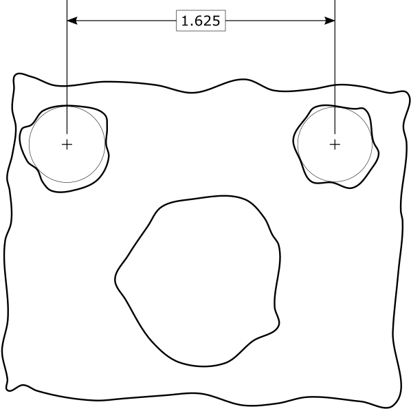
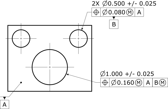
Suppose you had the following specification, using a secondary datum pattern referenced at MMB:
Solving the datum reference frame might result in the this illustration:
The solid lines are the actual surface, the gray shaded areas represent the datum zones, and the small dots represent the datum axis that must be in the zone. The left datum has a bigger zone because the left actual datum hole is larger. The sizes of the zones are exaggerated to show how things work.
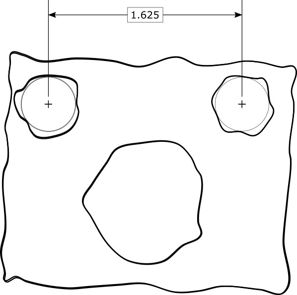
Since the datum axes are allowed to move within the datum zones (but not go outside them), that means the actual value for the position tolerance can be zero. Here is an illustration of how this works:
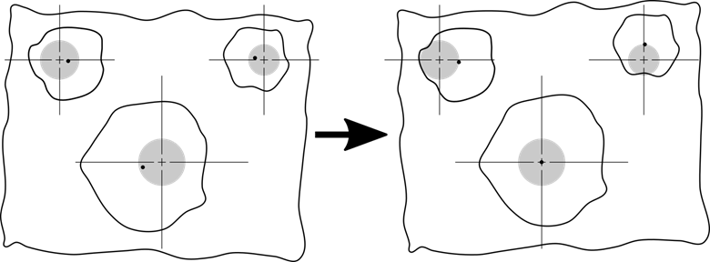
On the left is before optimization, showing the axis and tolerance zone of the big hole. On the right is after optimization, where the axis of the big hole is optimized to perfect location (yielding zero actual value) while the datum axes are forced to remain inside their zone but are not optimized.
The surfaces are shown to aid understanding, but they do not participate in the optimization. The optimization only uses the zones and the axes.
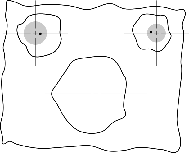
However, if the big hole has a large enough position error, the measured value will not be zero. Below is an illustration of such a case:
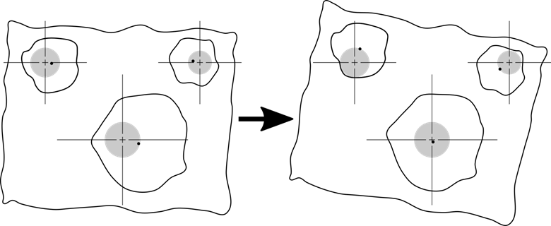
The big hole's actual value is optimized to be as small as possible, but the datums need to stay in their zones and so the actual value isn't zero.
When you reference a datum with a material boundary modifier, the geometric tolerance command needs to compute the size of the material boundary unless the material boundary size is specified. The material boundary size is based on the size tolerance of the datum feature and the applicable geometric tolerances.
For datums with a maximum material modifier, you start with the maximum material condition size. This is the upper limit of size for outer features, and the lower limit of size for inner features. Then you adjust this size by the applicable geometric tolerance.
For datums with a least material modifier, you start with the least material condition size. This is the lower limit of size for outer features, and the upper limit of size for inner features. Then you adjust this size by the applicable geometric tolerance.
For material boundaries that contain the feature surface, the applicable geometric tolerance increases the size of the material boundary. This is for outer features with a maximum material modifier and for inner features with a least material modifier.
For material boundaries that are contained by the feature surface, the material boundary size is decreased by the applicable geometric tolerance. This is for inner features with a maximum material modifier and for outer features with a least material modifier.
The rules that determine which geometric tolerance to apply, if any, are complicated. They are described in ISO 2692 and incompletely described in ASME Y14.5. The PC-DMIS rules are shown below. In the ISO case, the rules are adapted to the tolerance types that PC-DMIS supports. In the ASME case, the rules are extrapolated from the incomplete description in Y14.5.
For primary datums with ISO, we adjust the material boundary by the form tolerance at the same material condition, if it exists:
If the primary datum is a cylinder, we use the axis straightness at the same material condition, if it exists.
If the primary datum is a sphere or width, we ignore the form tolerance and do not adjust the material boundary.
If the primary datum is A
and datum
cylinder A is a shaft and has an axis straightness at ,
the maximum material boundary is the maximum size of the shaft plus the
axis straightness tolerance.
For secondary datums with ISO, we adjust the material boundary by the orientation or location tolerance at the same material condition that references the same primary datum, with the same datum modifiers, and that does not have any secondary datum. All other tolerances are ignored. If more than one such tolerance exists, the material boundary adjustment uses the smallest such tolerance.
For tertiary datums with ISO, we adjust the material boundary by the orientation or location tolerance at the same material condition that references the same primary datum, with the same datum modifiers, and that references the same secondary datum, with the same datum modifiers, and that does not have any tertiary datum. All other tolerances are ignored. If more than one such tolerance exists, the material boundary adjustment uses the smallest such tolerance.
For primary datums with ASME, we adjust the material boundary by the axis straightness form tolerance, if it exists. We do not adjust the material boundary for spheres and widths.
If the primary datum is A
and datum
cylinder A is a shaft and has an axis straightness, the maximum material
boundary is the maximum size of the shaft plus the axis straightness tolerance.
In rare cases, a pattern is used as a primary datum with a material boundary modifier. In such cases, we first look for a position tolerance on the pattern without datums. If the position tolerance exists, PC-DMIS adjusts the material boundary by the position tolerance value. If no such position exists, then we look for an axis straightness tolerance.
For secondary datums with ASME, we adjust the material boundary by the orientation or position tolerance on the secondary datum.
for a single datum, we use the orientation tolerance of the datum to the primary datum
if no such orientation tolerance exists, we use the position tolerance of the datum pattern to the primary datum with the same datum modifiers
for a datum pattern, we use the position tolerance of the datum pattern to the primary datum with the same datum modifiers
for a common datum, we use the simultaneous position tolerances of the common datum features to the primary datum with the same datum modifiers
the only geometric tolerances that are considered are specified at the same material condition as the secondary datum in question, and have no secondary datum
For tertiary datums with ASME, we adjust the material boundary by a position tolerance on the tertiary datum (not orientation). The position tolerance must reference the same primary and secondary datums, with the same datum modifiers, without any tertiary datum. The position tolerance must be at the same material condition as the tertiary datum in question. If no such position tolerance is found, the material boundary is not adjusted by any geometric tolerance. For a single datum, the position tolerance must reference that feature. For a datum pattern, the position tolerance must reference the pattern. For a common datum, there must be simultaneous position of the common datum features.
An ASME datum with a translation modifier, or an ISO datum, has unrestricted translation compared to higher-precedence datum simulators. Both the ASME and ISO standards are unclear about what this means when there are any datums referenced with a material modifier.
Suppose we take a primary datum plane, a secondary datum circle at maximum material, and a tertiary datum circle without a material modifier but with translation allowed. There are two possible interpretations:
We could evaluate the datum reference frame independent of the position tolerance; we optimize the B-C distance so that B is optimally centered in its hole, and then we keep that distance constant while evaluating the position tolerance.
We could evaluate the datum reference frame simultaneously with the position tolerance; while optimizing the position tolerance we allow the B-C distance to vary until the position tolerance measured value is as small as possible.
In PC-DMIS, we use the first interpretation because it is more conservative (the measured values are larger).