
In this Topic Hide
A circular runout specification controls how much the feature’s surface cross sections can deviate from being perfect circles centered on some datum axis.
Actual Value:
For a cross section, this is the minimum distance between two circles.
These circles are centered on and oriented perpendicular to the datum
axis. They contain the entire cross section between them.
For a whole feature, this the worst actual value of all the cross sections.

With the above specification, the actual value for one of the cross sections looks like this:
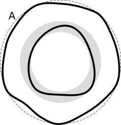
The actual part surface uses the solid line, the actual datum uses the dashed line, and the smallest tolerance zone containing the cross section's surface is shown in the shaded area. The tolerance zone is exactly coaxial to the actual datum axis. The actual value for the whole feature is the worst actual value of all the cross sections.
Finally, the measured value (with DEFAULT datum math) for one of the cross sections looks like this:

The measured tolerance zone is exactly coaxial to the measured datum axis. In this case, the measured points were not measured densely enough, and so the measured value is smaller than the actual value. The measured value for the whole feature would be the worst measured value of all the cross sections.
You can use circular, cylindrical, conical, or planar features that have surface data. For details on the circles, cylinders, cones, and planes that have surface data, refer to "Feature Types With and Without Surface Data". These features must be nominally concentric with the datum axis.
This geometric tolerance interprets circular features as a single cross section.
Measured Value:
This is the distance between two circles. The circles contain all the measured
points between them. The circles are centered on and perpendicular to
the datum axis.
Usually, the two circles are coplanar. This means the surface has zero conical angle. However, the "cone half angle" option in the command lets you specify a conical surface. In that case, PC-DMIS angles the two circles so that the tolerance zone is perpendicular to the nominal surface. The cone half angle represents the angle of the nominal surface, not the tolerance zone.
For outer circles, positive angles mean the circle vector points towards the cone vertex, and negative angles mean the circle vector points away from the cone vertex.
For inner circles, positive angles mean the circle vector points away from the cone vertex, and negative angles mean the circle vector points towards the cone vertex.
These inner and outer conventions were chosen to represent typical defaults. Most of the time, outer circle vectors point toward the cone vertex—the positive angle case. Also, most of the time, inner circle vectors point away from the cone vertex—the positive angle case.
Suppose you have the following specification, and you decide to measure the cone as a series of circles (even though we recommend using a cone feature):
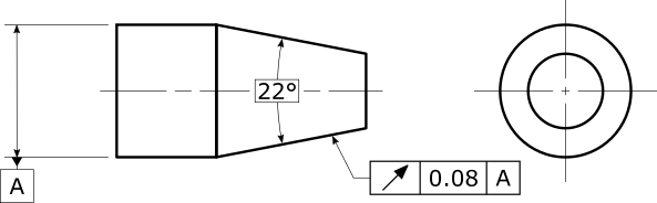
In that case, the circles are outer circles, which means if the circle's vector points to the right (towards the cone vertex), the cone half angle should be set to +11°. If the circle's vector points to the left (away from the cone vertex), the cone half angle should be set to -11°.
This geometric tolerance divides up the data from a cylindrical feature into multiple cross sections. The tolerance evaluates the runout on each cross section. To maximize your chances of finding the worst actual cross section, we recommend that you measure the cylinder with many cross sections
Measured Value:
Across the entire feature, this is the measured value of the worst cross
section. If you didn't measure the measured data in cross sections, PC-DMIS
gives you an error.
This geometric tolerance divides up the data from a conical feature into multiple cross sections. The tolerance evaluates the runout on each cross section. It orients each tolerance zone perpendicular to the nominal surface. To maximize your chances of finding the worst actual cross section, we recommend that you measure the cone with many cross sections.
Measured Value:
Across the entire feature, this is the measured value of the worst cross
section. If you didn't measure the measured data in cross sections,
PC-DMIS gives you an error.
This geometric tolerance divides up the data from a planar feature into one or more circular sections around the datum axis. The tolerance orients each tolerance zone perpendicular to the nominal surface. To maximize your chances of finding the worst actual circular section, we recommend that you measure the plane with many circular sections.
Measured Value:
Across the entire feature, this is the measured value of the worst circular
section. If you didn't measure the measured data in circular sections
that surround the datum axis, PC-DMIS gives you an error.
The datum reference frame must establish a clear datum axis.
None. This geometric tolerance does not allow modifiers.
For circular features, the "cone half angle" option allows the circle to represent a cross section of a conical surface, instead of a cylindrical surface. This adjusts the orientation of the tolerance zone. Both positive and negative cone half angles make sense, which allows you to control whether the nominal cone opening direction is parallel or antiparallel to the nominal circle's vector.
For inner circles with positive cone half angles, the circle vector points from smaller cone diameters to larger cone diameters. Negative cone half angles are the reverse. This convention was chosen because it makes positive angles be the most common case for most users.
For outer circles with positive cone half angles, the circle vector points from larger cone diameters to smaller cone diameters. Negative cone half angles are the reverse. This convention was chosen because it makes positive angles be the most common case for most users.
When at least one datum feature has surface data, the datum math type controls how to compute the measured datums from the datum features’ surface data. For more information, see "How PC-DMIS Solves and Uses Datums".
Here is an example report for a circular runout tolerance of a cylinder.
