In this Topic Hide
A concentricity specification controls how much the feature can deviate from being concentric to one or more datums.
For this geometric tolerance, these three aspects work together:
Each considered feature and each resulting toleranced feature
Each tolerance zone
The datum features
To evaluate this tolerance, PC-DMIS converts each considered feature to a toleranced feature. You can find this described in "Deriving the Toleranced Feature”.
PC-DMIS then optimizes each toleranced feature into its respective tolerance zone. The optimization process respects whatever constraints each datum imposes.
You can use these feature types:
3D constructed BF lines, cast lines, generic lines, cylinders, circles, spheres, and cones
PC-DMIS constructs the toleranced feature based on the standard you use (ASME Y14.5 or ISO 1101).
ISO 1101 (or with a feature that does not have surface data):
PC-DMIS constructs the toleranced feature in the same way as position tolerances do.
ASME Y14.5 with cylinders, circles, spheres, and cones with surface data:
PC-DMIS provides an option to switch between MEDIAN_POINTS or AXIS:
AXIS - The software constructs the toleranced feature as the axis of the unrelated mating envelope (this is the same as position tolerances).
MEDIAN_POINTS - The software constructs the toleranced feature from all the median points of the feature. It does this according to paragraph 7.6.4.2.2 of ASME Y14.5 2009.
For ISO, the tolerance zone shape is always diametric. It is oriented parallel to the datum axis.
For ASME, the tolerance shapes are usually diametric, but sphere features can have a spherical or a diametric zone.
There is one special case to consider. If you have a spherical-zone concentricity of two or more spheres (thus, ASME concentricity) it is not clear from the standard whether the spheres should be considered simultaneously or independently. The PC-DMIS geometric tolerance command considers them simultaneously, since this is the more conservative choice.
Actual Value:
This is the size of the smallest tolerance zone that contains the actual
toleranced feature. The zone is nominally oriented and located to each
actual datum.
Measured Value:
This is the size of the smallest tolerance zone that contains the measured
toleranced feature. The zone is nominally oriented and located to each
measured datum.
Suppose you have this concentricity specification:

With the above specification, the actual value looks like this:
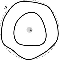
The actual part surface uses the solid line, the actual datum uses the dashed line, the toleranced feature uses the dotted line, and the smallest tolerance zone that contains the actual toleranced feature is shown in the shaded area. The tolerance zone is exactly concentric to the axis of the actual datum.
Finally, the measured value (with DEFAULT datum math) looks like this:
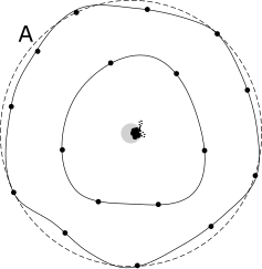
The measured tolerance zone is exactly concentric to the axis of the measured datum. In this case, the measured points were not measured densely enough, and so the measured value is smaller than the actual value.
All input features (considered and datum) must have the correct specified nominal values. This ensures that the measured values are calculated correctly, and that the tolerance command correctly identifies the optimizable degrees of freedom.
The datum reference frame must be axial, and the considered feature surface or surfaces must be nominally concentric with the datum axis.
When the considered feature
is a cylinder, circle, or sphere, concentricity tolerances referencing
ISO 1101 allow a maximum material modifier  to indicate
the specification is at the maximum material condition (MMC). Alternatively,
they allow a least material modifier
to indicate
the specification is at the maximum material condition (MMC). Alternatively,
they allow a least material modifier  to indicate
the specification is at the least material condition (LMC). This means
that as the unrelated mating envelope size (or unrelated minimum material
envelope size for LMC) deviates from the MMC (or LMC), additional tolerance
or "bonus" tolerance is added to the tolerance in the feature
control frame, yielding a total tolerance. For more information on this
bonus tolerance, see "Evaluating
Size with the Geometric Tolerance Command".
to indicate
the specification is at the least material condition (LMC). This means
that as the unrelated mating envelope size (or unrelated minimum material
envelope size for LMC) deviates from the MMC (or LMC), additional tolerance
or "bonus" tolerance is added to the tolerance in the feature
control frame, yielding a total tolerance. For more information on this
bonus tolerance, see "Evaluating
Size with the Geometric Tolerance Command".
Concentricity tolerances have a feature math type when the considered feature has surface data.
This math type controls how to compute the toleranced feature from the considered feature's surface data. For more information, see "Deriving the Toleranced Feature".
When at least one datum feature has surface data, the datum math type controls how to compute the measured datums from the datum features' surface data. For more information, see "How PC-DMIS Solves and Uses Datums".
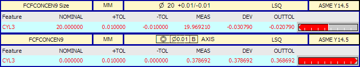
Here is an example report for a concentricity tolerance of a cylinder. The cylinder's size tolerance is in the upper label, and the concentricity is in the lower label.