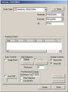
The Manual Freeform scan lets you create a freeform scan with a hard probe. This scan doesn't require an initial or direction vector like many of the other manual scans. Similar to its DCC counterpart, all you need to do to create a freeform scan is to click points on the surface you wish to scan.
For information on this tab's other controls, see the "Common Functions of the Scan Dialog Box" topic in the "Scanning Your Part" chapter in the PC-DMIS Core documentation.
To create a Manual Freeform scan:
Select the Insert | Scan | Manual Freeform menu option to open the MANUAL FREEFORM dialog box.

Manual Freeform dialog box
Specify a custom name for the scan in the ID box if you don't want to use the default name.
If you're using a CAD model, type a Find Nominals tolerance in the Find Nominals Control area. This defines how far away the actual ball center point can be from the nominal CAD location.
Click on the surface of the part in the Graphic Display window to define your scan's path. With each click, an orange point appears on the part drawing. Each new point connects to the previous point with an orange line.
Once you have sufficient points for your scan, click Create. PC-DMIS inserts the scan into the Edit window.