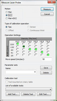
The options on the Measure Laser Probe dialog box determine the procedure that the software uses for the laser sensor calibration. To access this dialog box, open the Probe Utilities dialog box (Insert | Hardware Definition | Probe), and then click Measure.
Measure Laser Probe dialog box
Change the following options as needed or as directed in "Step 4: Calibrate the Laser Sensor".
Motion
Man - This option requires that you manually position the arm in several different locations that bisect the calibration tool. This varies based on the sensor manufacturer. This option is the only available motion option for arm machines.
DCC - Use this mode when the laser sensor has accurate offsets provided by the sensor manufacturer or if you have already run the calibrate "offset" routine. This moves the machine through a series of positions as recommended by the sensor manufacturer. You are not required to position the sensor manually for each tip that is calibrated.
Man+DCC - This mode is similar to DCC mode, except that you must position the sensor over the sphere to begin the calibration sequence for each of the tips to calibrate. The software prompts you to position the sphere at the beginning of the calibration process.
Types of Calibration Operations
The options in this section are available based on the laser sensor. Tips works for all probes, and Offset is only for Perceptron sensors.
Tips - Use this option to do a standard calibration for all marked tips for your laser sensor.
Offset - Use this option to estimate the laser sensor offset for Perceptron laser sensor types. You only need offset calibrations to position the machine correctly to calibrate tips. If you skip this step, the probe may miss the sphere during tip calibration.
When you calibrate Perceptron sensors for the first time:
With the Offset option, calibrate a single tip.
With the Tips option, calibrate the first tip angle and any other tip angles.
Operation Settings
The items that appear in this area vary based on the laser sensor type.
Sensor states - As described in the "Scan Zoom States (for CMS Sensors)" topic, these options appear only for CMS sensors. You can use these options to select a predefined sensor state. Each state has a specific combination of sensor frequency, data density, and Field of View (FOV) width.
Move Speed [%] - Determines the percentage of the maximum machine speed that the software uses during the calibration process.
Parameter sets
Parameter sets allow you to create, save, and use saved sets for your laser sensor. This information is saved with the probe file, and it includes the settings for your laser sensor.
To create your own named parameter sets:
Modify any parameters on the Measure Laser Probe dialog box.
From the Parameter Sets area, in the Name box, type a name for the new parameter set, and click Save. To delete a saved parameter set, select it, and click Delete.
Calibration Tool
Select the appropriate calibration tool. If this is your first calibration, you need to click Add Tool to first define the calibration tool. For specific information on defining a qualification tool, see the "Defining Hardware" chapter of the PC-DMIS Core documentation.
Make sure you use the spherical qualification tool that comes with your laser sensor. The surface characteristics of this tool are designed for optimal scanning results. If you use a tool made by another manufacturer, it may produce inaccurate data.