The Simulate Pointcloud function allows you to create and view the pointcloud from the Scan dialog box (Linear, Freeform, and so on) when the CMM is in Offline mode.
Using the laser probe orientation, field of view and scan settings, the software projects the laser lines onto the CAD model. This way you can see if the simulated pointcloud is acceptable and make changes if needed for an individual scan. PC-DMIS holds the simulated points in a COP.
Adjust the settings found on the Animation tab of the Setup Options dialog box (Edit | Preferences | Setup) to control the speed of the simulated laser scan. For details, see "Using the Animation Parameters for Pointcloud Simulation".
Follow the "Getting Started" chapter to define the active sensor tip and scan speed. If you like, you can pre-define the laser width and density of the scan from the Measure Laser Probe dialog box when you define the sensor. To access this dialog box, open the Probe Utilities dialog box (Insert | Hardware Definition | Probe), and then click Measure. For details on laser probe measurement options, see "Measure Laser Probe Options".
Define the scan path properties from any Scan dialog box (linear, freeform, and other properties). You can also define the laser width and density settings from the same dialog box. For details, see "Scan Zoom States (for CMS Sensors)".
Click the Simulate button from any Scan dialog box to display the pointcloud in the Graphic Display window. You can also simulate the pointcloud when you execute the scan from the Edit window in Offline mode.
After you create the scans, you can execute the entire offline measurement routine and display all scans in different probe orientations. This allows you to check if you can extract scanned Auto Features (for example) based on the scan settings.
Warning: If the CMM is online and the Simulate button is pressed on the Laser Scan dialog box (Freeform, Linear Open, etc.), the software immediately drives the machine and scans online. To prevent injury, make sure you are clear of the machine prior to pressing the button.
Example Using the Simulate Pointcloud Function
For example, to use the Simulate pointcloud function on a linear open scan:
Create a COP (Insert | Pointcloud | Feature). For details on pointcloud features and creating a COP, see the "Using Pointclouds" chapter.
Set the scan speed. For details, see "Getting Started".
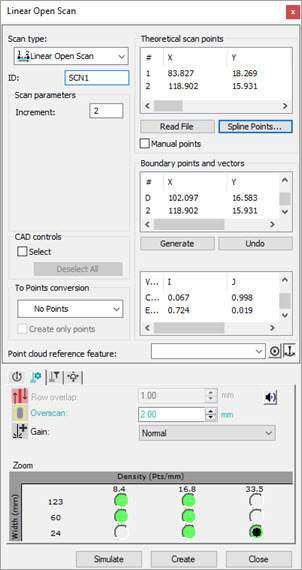
Open the Linear Open Scan dialog box (Insert | Scan | Linear Open).
In the Scan parameters section, set the Increment value.
At the bottom of the dialog box, click the Laser Scan Properties tab, and set these options:
Enter the Overscan value.
Select the Gain option from the list.
Select the stripe Width and scan Density setting.
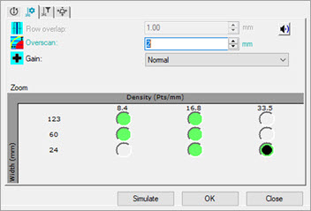
Laser Scan Properties tab
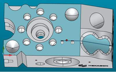
In the Graphic Display window, click the three points on the CAD model to define the boundary points and vectors.
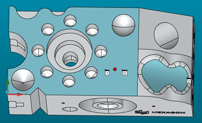
Example showing the three points to set up the scan
From the Boundary points and vectors section, click Generate.
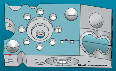
Example showing a Linear Open scan generated
From the Theoretical Scan Points section, click Spline Points.
Example showing a Linear Open scan splined
Click the Simulate button to show the simulated pointcloud based on the current probe orientation (active tip) and laser scan settings.
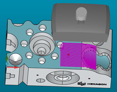
Example showing the Pointcloud Simulation in progress
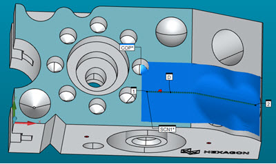
Example showing the Pointcloud Simulation completed
If needed, you can make changes to the scan and simulate it to check the results.
When everything looks correct, click the Create button to implement the scan in your measurement routine.