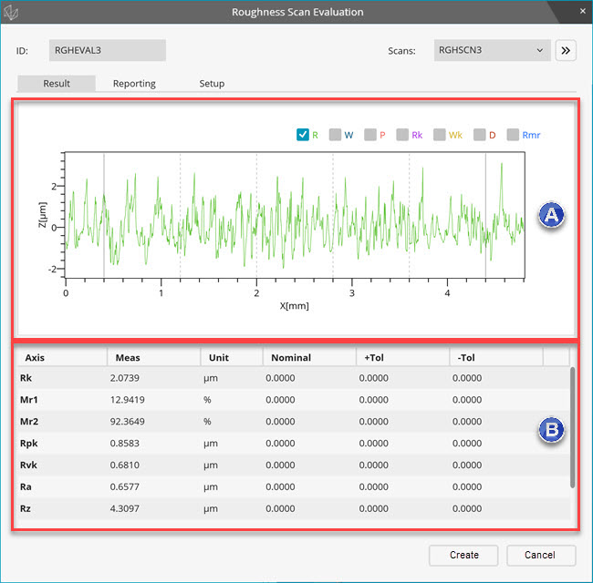
The Result tab in the Roughness Evaluation dialog box (Insert | Dimension | Roughness) displays the calculated roughness characteristics.
The top area of the Result tab displays the plot and the bottom area displays the results of the measurement.
Result tab
Plot area - This area lets you select the check boxes to display one or more plots. If you position your mouse pointer over any of the check box, the tooltip displays the information about it. The Rmr plot is always combined with R plot. The PC-DMIS report also displays the same plot.
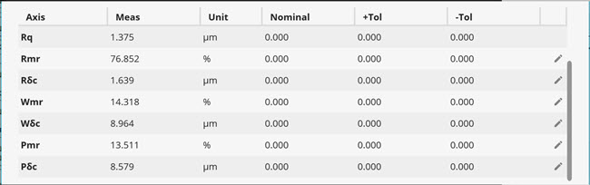
Result area - This area shows the results of the characteristics selected in the Setup tab.
Axis Rmr, Wmr, Pmr - An evaluation of Rmr needs additional parameters. In the Results area, click the Edit icon on the Rmr row to open the Edit Parameters dialog box.
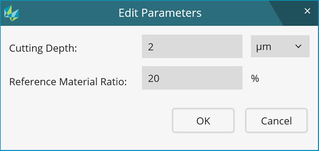
Edit Parameters dialog box
Cutting Depth - Type the value. The value you enter is in the units you select from the list. The list contains these items: microns, % of Rt, or % of Rz.
Reference Material Ratio - Type the value. PC-DMIS calculates Rmr based on the input values.
Axis
 ,
,  ,
, - In the Results area, click the Edit
icon on the Rmr row to open the Edit Parameters
dialog box.
- In the Results area, click the Edit
icon on the Rmr row to open the Edit Parameters
dialog box.
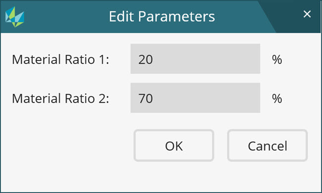
Edit Parameters dialog box
Type the values in Material Ratio 1 and Material Ratio 2 boxes. The default values are 20 and 70 respectively.
Right-click anywhere in this area to display two menu options:
Show selected axes - Select this option after modification of the selection of characteristics in the Setup tab.
Delete - Select this option to delete one or more characteristics. You can also use the Delete key.
To re-order characteristics, select the characteristic, press Shift, and drag it to the desired location.
To add nominal values and tolerances, click the cell and type the desired value.
To edit the roughness evaluation parameters, select
the Advance button ( ).
The Evaluation Parameters area appears:
).
The Evaluation Parameters area appears:
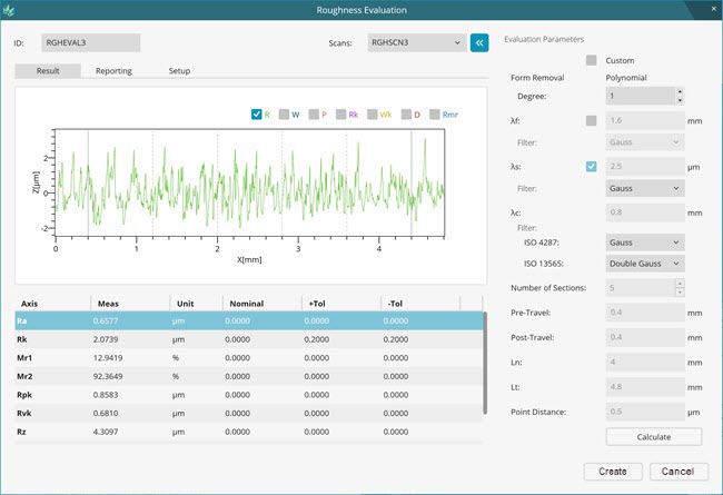
Custom check box - The Roughness Evaluation command reads the parameters from the selected Roughness scan command. The parameters are read whenever you edit or execute an Evaluation command. You can only select the desired filters that are not recorded in the Roughness scan command. The advantage of this method is that if any parameter is modified in the Roughness scan command, it automatically applies in Roughness Dimension command.
You might want to modify the parameters in dimension commands. To do this, select the Custom check box. If you select the Custom check box, parameters in dimension commands are not read at the time of edition or execution. The parameters stored in dimension commands are used for the evaluation of roughness characteristics.
Form Removal box - To remove the form error, the polynomial filter is available. Enter the desired degree of polynomial. The default is 1.
λf - To apply the λf filter, do the following:
Mark the check box. By default, this check box is cleared.
Type the wavelength value in the box.
Select the Gauss or Robust Gauss filter in the Filter list.
λs - To apply the λs filter, do the following:
Mark the check box. By default, this check box is unmarked.
Type the wavelength value in the box. The default value is the wavelength that is set in the Roughness scan command.
Select the Gauss or Robust Gauss filter in the Filter list.
λc - To set the wavelength for the λc filter, do the following:
Type the wavelength value in the box. The default value is the wavelength that is set in the Roughness scan command.
Select the Gauss or Robust Gauss filter for ISO 4287 and ISO 13565 characteristics in the Filter lists.
Number of sections list - Select the number of sections for R profile in this box. The default value is the number that is set in the Roughness scan command. The number of sections for P profile characteristics is always 1 as per standard. The number of sections for W profile is set to 1 by default.
To set the number of sections for W profile equal to the number of sections for R profile, do the following:
Mark the Custom check box
Right-click on the Number of sections label and mark the Set number of sections for W profile equal to that for R profile check box.
Pre-Travel box - Type the pre-travel distance. By default, the value is the distance that is set in the Roughness scan command.
Post-Travel box - This box is for informational use only and is not editable. It displays the calculation. Post travel = Ln - Lt - Pre-travel.
Ln box -The evaluation length is a calculated number that appears for information only.
Lt box - The traverse length is the length of the scan. This value is read from the Roughness scan command. The Ln value must be smaller than the Lt value. It appears for information only.
Point Distance - This value is read from the Roughness scan command. This is the distance between two points in the roughness scan.
Calculate button - To re-evaluate the roughness scan, select this button. If required, you can change the parameters and select the Calculate button.
More: