From the Edit menu, point to Graphic Display Window, and choose Lighting, Materials.
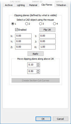
CAD and Graphic Setup dialog box - Clip Planes tab
The Clip Planes tab of the CAD and Graphic Setup dialog box allows you to define up to four planes, called "clipping planes" that you can use to hide the display of your part model on one side of the plane. Your part model on the other side of the plane remains visible. These planes allow you to create cross sections of your part model.
Clipping Planes appear in the Graphic Display window as round saw-like symbols.
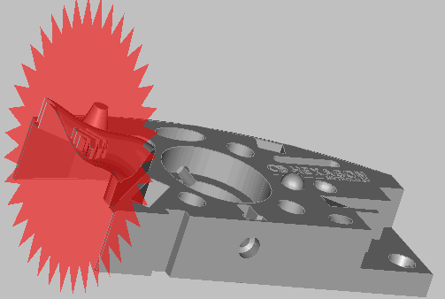
Example of a clipping plane creating a cross section of the Hexagon test block
More: