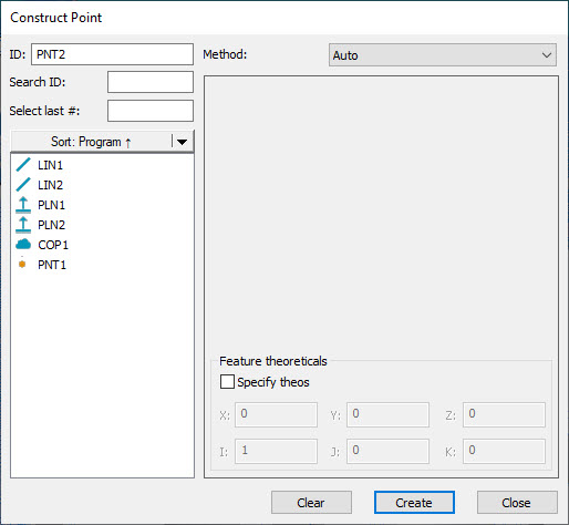
Construct Point dialog box
There are a number of ways to use PC-DMIS to construct a point. The following table lists the various types of constructed points along with their necessary inputs. Some features may require no inputs while others may require three inputs or more. In the table, the term "Any" indicates that the construction can take any type of feature as input for construction. PC-DMIS allows the features to be selected in any order.
Construct Feature Type |
Edit Window Symbol |
Number of Required Input Features |
Primary Feature |
Secondary Feature |
Tertiary Feature |
Comments |
Auto Point |
- |
- |
- |
- |
- |
See "Auto Point Construction". |
Intersect Point |
INTOF |
2 |
See topic below for valid features. |
See topic below for valid features. |
- |
Constructs a point at the intersection of the linear attribute of two features. |
Origin Point |
ORIGIN |
0 |
- |
- |
- |
Constructs a point at the alignment origin. |
Drop Point |
DROP |
2 |
Any |
Cone, Cylinder, Line, Slot |
- |
First feature is dropped onto the second line feature. |
Cast Point |
CAST |
1 |
Any |
- |
- |
Constructs a point at the centroid of the input feature. |
Mid Point |
MID |
2 |
Any |
Any |
- |
Constructs a mid point between the centroids of the inputs. |
Corner Point |
CORNER |
3 |
Plane |
Plane |
Plane |
Constructs a point at the intersection of three planes. |
Project Point |
PROJ |
1 or 2 |
Any |
Plane |
- |
One input feature will project the point to the workplane. |
Pierce Point |
PIERCE |
2 |
See topic below for valid features. |
See topic below for valid features. |
- |
Constructs a point where one feature pierces the surface of another feature. |
Vector Distance Point |
VECT_DIST |
2 |
Any |
Any |
- |
Constructs a point at a distance from the second feature along the line from the two input features. |
Offset Point |
OFFSET |
1 |
Any |
- |
- |
Requires three offsets corresponding to X,Y, and Z. |
Tertiary Datum Point |
TERTIARY_DATUM |
1 |
Point, Plane, Line, Set of Points |
(Additional Point features if first feature is a point) |
(Additional Point features if first feature is a point) |
Constructs a point which simulates a tertiary datum that is external to material. |
Extracted Edge Point |
EXTRACTED_EDGE_POINT |
1 |
COP or Mesh |
- |
- |
Extracts and constructs a point from the selected COP or Mesh command. |
Extracted Surface Point |
EXTRACTED_SURFACE_POINT |
1 |
COP or Mesh |
- |
- |
Extracts and constructs a surface point from the selected COP or Mesh command. |
If you select inappropriate feature types, PC-DMIS displays "Cannot construct [feature]. Combination of input features not accepted." on the status bar.
To construct a point, do the following:
Open the Construct Point dialog box (Insert | Feature | Constructed | Point).
From the Method list, select the feature type to construct.
From the Feature Selection list, select the features to use to create the constructed point. If the feature type requires you to select more than one feature, select the features in the order you want PC-DMIS to process them in: Primary, Secondary and Tertiary.
In the Parameters area, select and enter the values you want to apply to the selected method. The available parameters are dependent on the selected method. For example, if you choose Auto from the Method list, you can select the Specify theos check box in the Feature theoreticals area and then enter the X, Y, Z, I, J, and K values.
Click the Create button.
The Edit window command line for a sample point construction would read:
feature_name=FEAT/POINT,TOG1
THEO/x_cord,y_cord,z_cord,i_vec,j_vec,k_vec
ACTL/x_cord,y_cord,z_cord,i_vec,j_vec,k_vec
CONSTR/TOG2,TOG3,......
The actual Edit report displays in all capital letters.
TOG1= POLR or RECT
TOG2 = POINT
TOG3 = CAST / CORNER / DROP / INTOF / MID / OFFSET / ORIG / PIERCE / PROJ / TERTIARY_DATUM
The first three lines that display in the Edit window are the same for all constructed points. The fourth line is slightly different according to the type of feature you are constructing. To switch between the different types of points, place the cursor on TOG3 and press F7 or F8. (See "Command Mode Keyboard Functions" in the "Using the Edit Window" chapter.)
When two or more features are involved, PC-DMIS automatically determines the necessary order of the input features. This improves the accuracy of the measurement process.
AUTO is the default method of construction. This option automatically determines the best way to construct a point using the input feature or features. See "Auto Point Construction".
The following topics describe the options for constructing a point.
More:
Constructing an Intersection Point
Constructing a Point at the Origin
Constructing a Projected Point
Constructing a Vector Distance Point
Constructing a Tertiary Datum Point
Constructing an Extracted Edge Point