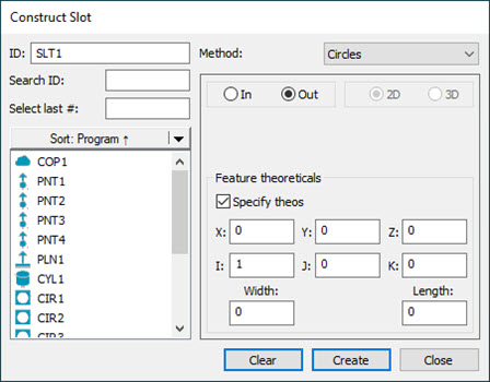
Construct Slot dialog box
There are two round slot types in PC-DMIS:
A round slot created from two circles (Circles option)
A round slot created from four or more inputs (Best Fit or BF Recomp option).
The table below shows the inputs for the slot and the editor definitions.
CONSTRUCT FEATURE TYPE |
SYMBOL IN EDIT WINDOW |
# OF INPUT FEATURES |
FEATURE #1: |
FEATURE #2: |
COMMENTS |
Round Slot |
CIRCLES |
2 |
Circle |
Circle |
Constructs a slot in the plane of the first circle from center to center. |
Round Slot |
BF |
4 or more |
- |
- |
Constructs a Best Fit slot using the given inputs. See the Note below for recommended inputs. |
Round Slot |
BFRE |
4 or more |
- |
- |
Constructs a Best Fit Recompensate slot using the given inputs. See the Note below for recommended inputs. |
Round Slot |
PROJ |
2 |
Slot |
Plane |
Constructs a Projected Round Slot onto the plane. |
Round Slot |
CAST |
1 |
Any |
- |
Constructs a round slot at the centroid of the input feature. |
For Best Fit (BF) or Best Fit Recompensate (BFRE) constructions, while you can use any feature type for your input features, BF and BFRE fit types are typically used with point features or point sets (a scan of points, a feature set with points, or an expression that resolves to an array of points).
If you select inappropriate feature types, PC-DMIS displays "Cannot construct [feature]. Combination of input features not accepted." on the status bar.
To construct a round slot:
Open the Construct Round Slot dialog box (Insert | Feature | Constructed | Round Slot).
From the Method list, select the method of the constructed round slot. The available options are:
Circles
Best Fit
BF Recomp
Projection
Cast
Using the table above, select the features from the Feature list based on the selected method.
Select the In or Out option. For details, see the "In / Out Slot" topic in this documentation.
If you chose one of the best fit methods, select either the 2D or 3D option. For details, see the "2D / 3D Slot" topic in this documentation.
If you want to change the feature theoretical values, select the Feature theoreticals check box and type in the values. For details, see the "Specifying Feature Theoreticals" topic in this documentation.
Click the Create button.
The Edit window command line for a sample Slot Construction would read:
feature_name=FEAT/SLOT,TOG1,TOG2,TOG3
THEO/x_cord,y_cord,z_cord,i_vec,j_vec,k_vec,width,length
ACTL/x_cord,y_cord,z_cord,i_vec,j_vec,k_vec,width,length
CONSTR/TOG4,TOG5,TOG6,TOG7,feat_1,feat_2, …
The actual report displays in all capital letters.
TOG1 = CARTESIAN or POLAR
TOG2 = OUT or IN
TOG3 = YES or NO
TOG4 = SLOT (or other construction type)
TOG5 = ROUND or SQUARE
TOG6 = CIRCLES or BF or BFRE or PROJ
TOG7 = 2D or 3D (This appears only if TOG6 reads BF or BFRE)
More: