
Pointcloud Toolbar
The Pointcloud toolbar provides all pointcloud operations, features, and functions. It is accessible from the View | Toolbars | Pointcloud menu depending on your system's configuration.
All options may not be available. Some options require specific licensing to enable them.
The following options are available from this toolbar:
 Pointcloud - This button opens the Pointcloud
dialog box that you can use to create pointcloud features. For details
on this dialog box and how to create pointcloud features, see "Manipulating Pointclouds"
in the "Using Pointclouds"
chapter of the PC-DMIS Laser documentation.
Pointcloud - This button opens the Pointcloud
dialog box that you can use to create pointcloud features. For details
on this dialog box and how to create pointcloud features, see "Manipulating Pointclouds"
in the "Using Pointclouds"
chapter of the PC-DMIS Laser documentation.
 Pointcloud Operator
- This button opens the Pointcloud Operator
dialog box that you can use to perform different operations on pointcloud
(COP) commands and other Pointcloud operator commands. For details on
this dialog box and how to create pointcloud operators, see "Pointcloud Operators" in
the PC-DMIS Laser documentation.
Pointcloud Operator
- This button opens the Pointcloud Operator
dialog box that you can use to perform different operations on pointcloud
(COP) commands and other Pointcloud operator commands. For details on
this dialog box and how to create pointcloud operators, see "Pointcloud Operators" in
the PC-DMIS Laser documentation.
 Pointcloud Mesh - This button opens the Mesh Command dialog box that you can use to define
a mesh command for pointclouds. For details, see "Creating
a Mesh Feature" in the PC-DMIS Laser documentation. This option
is only available if you have the Mesh and Big COP licenses.
Pointcloud Mesh - This button opens the Mesh Command dialog box that you can use to define
a mesh command for pointclouds. For details, see "Creating
a Mesh Feature" in the PC-DMIS Laser documentation. This option
is only available if you have the Mesh and Big COP licenses.
 Portable
Scanning Widget - This button displays the Portable
Scanning Widget toolbar. When you connect to a portable device,
and the active probe is a laser scanner, PC-DMIS automatically shows the
Portable Scanning Widget toolbar. For details
on the Portable Scanning Widget toolbar, see
"Portable
Scanning Widget Toolbar" in the PC-DMIS Portable documentation.
Portable
Scanning Widget - This button displays the Portable
Scanning Widget toolbar. When you connect to a portable device,
and the active probe is a laser scanner, PC-DMIS automatically shows the
Portable Scanning Widget toolbar. For details
on the Portable Scanning Widget toolbar, see
"Portable
Scanning Widget Toolbar" in the PC-DMIS Portable documentation.
 Pointcloud
Data Collection Parameters - This button opens the Laser
Data Collection Settings dialog box that you can use to define
data filtering and an exclusion plane for your pointcloud data. For details
on this dialog box, see the "Laser
Data Collection Settings" topic.
Pointcloud
Data Collection Parameters - This button opens the Laser
Data Collection Settings dialog box that you can use to define
data filtering and an exclusion plane for your pointcloud data. For details
on this dialog box, see the "Laser
Data Collection Settings" topic.
 Simulate
Pointcloud - This button opens the Simulate
dialog box. You can use the dialog box to select and import a pointcloud
file. PC-DMIS then simulates the scanning of the imported pointcloud data.
For details on simulating a scan of an imported pointcloud, see "Simulate
Scanning by Importing a Pointcloud" in this documentation.
Simulate
Pointcloud - This button opens the Simulate
dialog box. You can use the dialog box to select and import a pointcloud
file. PC-DMIS then simulates the scanning of the imported pointcloud data.
For details on simulating a scan of an imported pointcloud, see "Simulate
Scanning by Importing a Pointcloud" in this documentation.
 Pointcloud
Boolean Operation - This button opens the Pointcloud
Operator dialog box with the Boolean operator selected. For details
on the dialog box and on how to create a Boolean pointcloud operator,
see "BOOLEAN" in the "Pointcloud Operators" chapter
of the PC-DMIS Laser documentation.
Pointcloud
Boolean Operation - This button opens the Pointcloud
Operator dialog box with the Boolean operator selected. For details
on the dialog box and on how to create a Boolean pointcloud operator,
see "BOOLEAN" in the "Pointcloud Operators" chapter
of the PC-DMIS Laser documentation.
 Cross
Section Pointcloud - This button opens the Pointcloud
Operator dialog box with the CROSS SECTION option selected. Click
the drop-down arrow to display the Pointcloud Cross
Section toolbar:
Cross
Section Pointcloud - This button opens the Pointcloud
Operator dialog box with the CROSS SECTION option selected. Click
the drop-down arrow to display the Pointcloud Cross
Section toolbar:
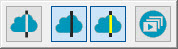
For details on pointcloud cross sections and how to use the Pointcloud Cross Section toolbar, see "CROSS SECTION" in the "Pointcloud Operators" chapter of this documentation.
 Clean Pointcloud - When you click this button,
the CLEAN operation immediately eliminates outlier COP points based on
the default MAX DISTANCE of the points to the CAD. If the distance of
a point is greater than the Max distance value,
the software considers the point as an outlier or not belonging to the
part. To use this operation, you must establish at least a rough alignment
(see "Creating
a Pointcloud/CAD Alignment") and a CAD model. For details on
the CLEAN pointcloud operator, see "CLEAN"
in the PC-DMIS Laser documentation.
Clean Pointcloud - When you click this button,
the CLEAN operation immediately eliminates outlier COP points based on
the default MAX DISTANCE of the points to the CAD. If the distance of
a point is greater than the Max distance value,
the software considers the point as an outlier or not belonging to the
part. To use this operation, you must establish at least a rough alignment
(see "Creating
a Pointcloud/CAD Alignment") and a CAD model. For details on
the CLEAN pointcloud operator, see "CLEAN"
in the PC-DMIS Laser documentation.
![]() Empty Pointcloud - When you click this button,
PC-DMIS immediately removes all the data from the currently selected COP.
Be aware that this change is permanent, so use with caution. For details
on the EMPTY pointcloud operator, see "EMPTY"
in the PC-DMIS Laser documentation.
Empty Pointcloud - When you click this button,
PC-DMIS immediately removes all the data from the currently selected COP.
Be aware that this change is permanent, so use with caution. For details
on the EMPTY pointcloud operator, see "EMPTY"
in the PC-DMIS Laser documentation.
 Filter Pointcloud
- This button opens the Pointcloud Operator
dialog box with the FILTER operation selected. The operation filters data
to a smaller subset of points. For details on the FILTER pointcloud operator,
see "FILTER" in the PC-DMIS Laser documentation.
Filter Pointcloud
- This button opens the Pointcloud Operator
dialog box with the FILTER operation selected. The operation filters data
to a smaller subset of points. For details on the FILTER pointcloud operator,
see "FILTER" in the PC-DMIS Laser documentation.
 Pointcloud Export - This button opens the Pointcloud Operator dialog box for the currently
selected export option.
Pointcloud Export - This button opens the Pointcloud Operator dialog box for the currently
selected export option.
For details on how to export supported file types, see "Pointcloud EXPORT" in the PC-DMIS Laser documentation.
Click the drop-down arrow to display the Pointcloud Export toolbar:
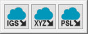
The options available are:
 Export Pointcloud in IGES Format - This button
opens the Pointcloud Operator dialog box with
the EXPORT IGES operation selected. The Export IGES operation exports
the data in a COP or operator command in IGES format to an IGES file.
Export Pointcloud in IGES Format - This button
opens the Pointcloud Operator dialog box with
the EXPORT IGES operation selected. The Export IGES operation exports
the data in a COP or operator command in IGES format to an IGES file.
 Export Pointcloud in XYZ Format - This button
opens the Pointcloud Operator dialog box with
the EXPORT XYZ operation selected. The Export XYZ operation exports the
data in a COP or operator command in XYZ format to an XYZ file.
Export Pointcloud in XYZ Format - This button
opens the Pointcloud Operator dialog box with
the EXPORT XYZ operation selected. The Export XYZ operation exports the
data in a COP or operator command in XYZ format to an XYZ file.
 Export Pointcloud in PSL Format - This button
opens the Pointcloud Operator dialog box with
the EXPORT PSL operation selected. The Export PSL operation exports the
data in a COP or operator command in PSL format to a PSL file.
Export Pointcloud in PSL Format - This button
opens the Pointcloud Operator dialog box with
the EXPORT PSL operation selected. The Export PSL operation exports the
data in a COP or operator command in PSL format to a PSL file.
 Pointcloud Import - This button opens the Pointcloud Operator dialog box for the currently
selected import option.
Pointcloud Import - This button opens the Pointcloud Operator dialog box for the currently
selected import option.
For details on how to import supported file types, see "Pointcloud IMPORT" in the PC-DMIS Laser documentation.
Click the drop-down arrow to display the Pointcloud Import toolbar:
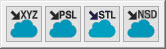
The options available are:
 Import Pointcloud in XYZ Format - This button
opens the Pointcloud Operator dialog box with
the IMPORT XYZ operation selected. The Import
XYZ operation imports data from an external file into a COP command in
the XYZ format.
Import Pointcloud in XYZ Format - This button
opens the Pointcloud Operator dialog box with
the IMPORT XYZ operation selected. The Import
XYZ operation imports data from an external file into a COP command in
the XYZ format.
 Import Pointcloud in PSL Format - This button
opens the Pointcloud Operator dialog box with
the IMPORT PSL operation selected. The Import
PSL operation imports data from an external file into a COP command in
the PSL format.
Import Pointcloud in PSL Format - This button
opens the Pointcloud Operator dialog box with
the IMPORT PSL operation selected. The Import
PSL operation imports data from an external file into a COP command in
the PSL format.
 Import Pointcloud in STL Format - This button
opens the Pointcloud Operator dialog box with
the IMPORT STL operation selected. The Import
STL operation imports data from an external file into a COP command in
the STL format.
Import Pointcloud in STL Format - This button
opens the Pointcloud Operator dialog box with
the IMPORT STL operation selected. The Import
STL operation imports data from an external file into a COP command in
the STL format.
 Import Pointcloud in NSD Format - This button
opens the Pointcloud Operator dialog box with
the IMPORT NSD operation selected. The .nsd
file contains X, Y, Z points inside a binary file. These files are typically
created by the 3DReshaper Meteor application.
Import Pointcloud in NSD Format - This button
opens the Pointcloud Operator dialog box with
the IMPORT NSD operation selected. The .nsd
file contains X, Y, Z points inside a binary file. These files are typically
created by the 3DReshaper Meteor application.
 Purge Pointcloud - When you click this button,
PC-DMIS immediately removes all data points that do not belong to this
operator. It is irreversible and affects all other operator commands that
refer to the same COP container, so use with caution. For details on the
Purge pointcloud operator command, see "PURGE"
in the PC-DMIS Laser documentation.
Purge Pointcloud - When you click this button,
PC-DMIS immediately removes all data points that do not belong to this
operator. It is irreversible and affects all other operator commands that
refer to the same COP container, so use with caution. For details on the
Purge pointcloud operator command, see "PURGE"
in the PC-DMIS Laser documentation.
 Reset Pointcloud - When you click this button,
PC-DMIS immediately reverses the most recent Surface Colormap, Point Colormap,
Select or Clean (unless Purge has been done) operations. For details on
the Reset pointcloud operator command, see "RESET"
in the PC-DMIS Laser documentation.
Reset Pointcloud - When you click this button,
PC-DMIS immediately reverses the most recent Surface Colormap, Point Colormap,
Select or Clean (unless Purge has been done) operations. For details on
the Reset pointcloud operator command, see "RESET"
in the PC-DMIS Laser documentation.
 Select Pointcloud
- Click this button to use the default Polygon selection method to select
and remove a portion of the COP.
Select Pointcloud
- Click this button to use the default Polygon selection method to select
and remove a portion of the COP.
After you click this button:
Click in the Graphic Display window to define the polygon vertices.
Press the Delete key to delete the last vertex.
Double-click your left mouse button or press the End key to close the polygon selection. PC-DMIS removes the portion of the pointcloud enclosed by the polygon.
Press the Esc key to abort.
For details on the Select pointcloud operator command, see the "SELECT" topic in the PC-DMIS Laser documentation.
The Select Pointcloud option differs from the use of the pointcloud operator as it immediately applies the function and is not added as a command. To create the command, open the pointcloud operator, and choose the Select method.
 TCP/IP - This button performs the currently
selected operation described below.
TCP/IP - This button performs the currently
selected operation described below.
Click the drop-down arrow to display the TCP/IP toolbar:

The options available are:
 TCP/IP Pointcloud Server receive data - This
button places PC-DMIS in a "watch" state, where it is ready
to receive a pointcloud file from a client application. The client application
must initiate sending the pointcloud data. This button only appears when
you run PC-DMIS in Offline mode.
TCP/IP Pointcloud Server receive data - This
button places PC-DMIS in a "watch" state, where it is ready
to receive a pointcloud file from a client application. The client application
must initiate sending the pointcloud data. This button only appears when
you run PC-DMIS in Offline mode.
 TCP/IP Pointcloud Server Connection with Local Copy
- This button establishes the connection with the client and sends the
pointcloud data directly to the client. When the scan finishes, the pointcloud
data remains inside the measurement routine.
For details on the TCP/IP Pointcloud server connection, see "TCP/IP
Pointcloud Server".
TCP/IP Pointcloud Server Connection with Local Copy
- This button establishes the connection with the client and sends the
pointcloud data directly to the client. When the scan finishes, the pointcloud
data remains inside the measurement routine.
For details on the TCP/IP Pointcloud server connection, see "TCP/IP
Pointcloud Server".
 TCP/IP Pointcloud Server Connection without Local Copy
- This button establishes the connection with the client and sends the
pointcloud data directly to the client. When the scan finishes, the pointcloud
data is deleted from the measurement routine.
For details on the TCP/IP Pointcloud server connection, see "TCP/IP
Pointcloud Server".
TCP/IP Pointcloud Server Connection without Local Copy
- This button establishes the connection with the client and sends the
pointcloud data directly to the client. When the scan finishes, the pointcloud
data is deleted from the measurement routine.
For details on the TCP/IP Pointcloud server connection, see "TCP/IP
Pointcloud Server".
 Pointcloud Alignment
- This button opens the Pointcloud/CAD Alignment
dialog box that you can use to create Pointcloud to CAD and COP to COP
alignments. For details, see "Pointcloud/CAD
Alignment Dialog Box Description" in the "Pointcloud
Alignments" chapter of the PC-DMIS Laser documentation.
Pointcloud Alignment
- This button opens the Pointcloud/CAD Alignment
dialog box that you can use to create Pointcloud to CAD and COP to COP
alignments. For details, see "Pointcloud/CAD
Alignment Dialog Box Description" in the "Pointcloud
Alignments" chapter of the PC-DMIS Laser documentation.
 Pointcloud
Colormap - This button opens the dialog box for the operator shown
on the button.
Pointcloud
Colormap - This button opens the dialog box for the operator shown
on the button.
Click the drop-down arrow to display the Pointcloud Colormap toolbar:

The Pointcloud Colormap toolbar allows you to select between the Surface Colormap, Point Colormap and Thickness Colormap options.
From left to right, the buttons are:
 Surface Colormap - This button opens the Pointcloud Operator dialog box with the Surface
Colormap operator selected. The SURFACE COLORMAP operation applies a colored
shading to the CAD model. The software shades the model according to the
deviations of the pointcloud compared to the CAD. The Pointcloud Surface
Colormap operator uses the colors defined in the Edit
Dimension Colors dialog box, and the tolerance limits specified
in the Upper tolerance and Lower
tolerance boxes.
Surface Colormap - This button opens the Pointcloud Operator dialog box with the Surface
Colormap operator selected. The SURFACE COLORMAP operation applies a colored
shading to the CAD model. The software shades the model according to the
deviations of the pointcloud compared to the CAD. The Pointcloud Surface
Colormap operator uses the colors defined in the Edit
Dimension Colors dialog box, and the tolerance limits specified
in the Upper tolerance and Lower
tolerance boxes.
You can create multiple
surface colormaps in a PC-DMIS measurement routine. However, only one
is active. The last surface colormap that was applied and created, or
the last one executed, is always the currently active colormap. You can
also select which colormap is the active one from the Colormaps
list box. You can also show or hide the active colormap from the Activate Colormap button ( )
on the Graphic Items toolbar, or from the menu
(Operation | Graphic Display Window | Graphic Items
| Activate Colormaps). For details on how to show and hide colormaps
with the Activate Colormap option, see the "Show / Hide Colormaps"
section in the "Surface Colormap"
topic.
)
on the Graphic Items toolbar, or from the menu
(Operation | Graphic Display Window | Graphic Items
| Activate Colormaps). For details on how to show and hide colormaps
with the Activate Colormap option, see the "Show / Hide Colormaps"
section in the "Surface Colormap"
topic.
When you activate a new colormap, PC-DMIS displays its associated scale with tolerance values and any annotations in the Graphic Display window.
To activate a colormap from the Colormaps list, click the Colormaps list box and select the colormap from the list of defined Colormap operators:
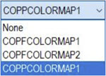
For details on the Pointcloud Surface Colormap operator, see "SURFACE COLORMAP" in the PC-DMIS Laser documentation.
 Point Colormap - This button opens the Pointcloud Operator dialog box with the Point
Colormap operator selected. The Point Colormap operation evaluates the
deviations of the data points contained in a COP command compared to a
CAD object. You can use this command to color the entire Pointcloud, or
to display the points as dots, needles and/or text. For details on the
Pointcloud Point Colormap operator, see "POINT
COLORMAP" in the PC-DMIS Laser documentation.
Point Colormap - This button opens the Pointcloud Operator dialog box with the Point
Colormap operator selected. The Point Colormap operation evaluates the
deviations of the data points contained in a COP command compared to a
CAD object. You can use this command to color the entire Pointcloud, or
to display the points as dots, needles and/or text. For details on the
Pointcloud Point Colormap operator, see "POINT
COLORMAP" in the PC-DMIS Laser documentation.
 Thickness Colormap - This button opens the Pointcloud Operator dialog box with the Thickness
Colormap operator selected. The Thickness Colormap allows you to show
and measure the part thickness as a colormap using only the Mesh or Pointcloud
(COP) data object. You can also compare the measured thickness to the
nominal CAD model thickness. For details on the Thickness
Colormap option, see "Pointcloud
Thickness Colormap" in this documentation.
Thickness Colormap - This button opens the Pointcloud Operator dialog box with the Thickness
Colormap operator selected. The Thickness Colormap allows you to show
and measure the part thickness as a colormap using only the Mesh or Pointcloud
(COP) data object. You can also compare the measured thickness to the
nominal CAD model thickness. For details on the Thickness
Colormap option, see "Pointcloud
Thickness Colormap" in this documentation.
More: