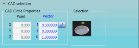
The options in the CAD selection group display the CAD coordinates for a Hole feature and enable you to perform CAD-related functions.
Feature Options
The following graphics show the options for each feature.
CD feature:

CAD selection group for CD feature
DI feature:
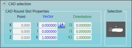
CAD selection group for DI feature
EI feature:
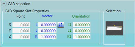
CAD selection group for EI feature
GD feature:
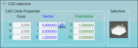
CAD selection group for GD feature
HD feature:
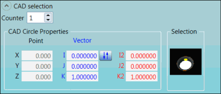
CAD selection group for HD feature
II feature:
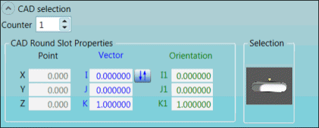
CAD selection group for II feature
Descriptions
The following table describes the options.
For descriptions of the icons that appear in the CAD selection group, see "Using the Icons".
Item |
Description |
Counter list |
Select the number of ESF features of this type in the measurement routine. |
CAD Circle Properties, CAD Square Slot Properties, and CAD Round Slot Properties areas |
X, Y, and Z Point boxes: These boxes display the calculated point locations on the CAD model. I, J, and K Vector boxes: These boxes display the calculated vector locations on the CAD model. I1, J1, and K1 Orientation boxes: These boxes display the calculated angle locations on the CAD model. |
Selection area |
This image appears when PC-DMIS is in Surface mode. This mode makes a solid model's surfaces selectable when you click on the CAD data in the Graphic Display window. This image displays the navigation path. |
Selection area
|
This image appears when PC-DMIS is in Curve mode. This mode makes a wireframe's model of curves and lines selectable when you click on the CAD data in the Graphic Display window. This image displays the navigation path. |
For more information about Surface mode and Curve mode, refer to "Switching Between Curve and Surface Modes" in the "Editing the CAD Display" chapter in the PC-DMIS Core documentation.
More: