Using the Icons

The following icons appear in the groups in the Extended Sheet Metal Features dialog box. The icons that appear depend on the feature you are creating.

CAD Selection Group

Item

Description

Snap to CAD Grid icon

Snap to CAD Grid icon: Snaps the point to the nearest grid intersection. You can use the snap to grid functionality even when the 3D grid is not showing.

Apply changes icon

Apply changes icon: Applies your changes and refreshes the values.

Flip Surface vector icon

Flip Surface vector icon: Reverses the direction of the surface vectors, causing the vector arrows to point in the opposite direction.

Flip Edge vector icon

Flip Edge vector icon: Reverses the direction of the edge vectors.

Get CAD point from last feature icon

Get CAD point from last feature icon: Copies the feature definition settings from the last feature that you created.

If your measurement routine does not contain any features, a message appears and indicates that no features exist in the measurement routine.

Select feature to get CAD point icon

Select feature to get CAD point icon: Copies the feature definition settings from an existing feature. When you click the icon, the Feature Selection dialog box appears and displays the ID of each feature in your measurement routine. Here is an example of the dialog box for the AA feature for the Point measuring principle:
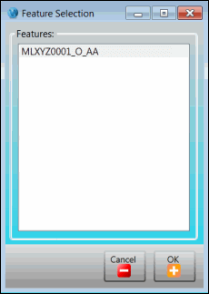
Feature Selection dialog box

Select the ID with the settings that you want to copy, and then click the OK button. To close the dialog box without copying any settings, click the Cancel button.

If your measurement routine does not contain any features, a message appears and indicates that no features exist in the measurement routine.

For more information about feature definition settings and the feature ID, refer to the appropriate help topic:

General Feature Parameters Group

Item

Description

Apply changes icon

Apply changes icon: Applies your changes and refreshes the values.

Show Path Lines icon

Show Path Lines icon: Displays the path lines your probe takes on the part while the probe measures marked features. These lines are called path lines. Path lines help you preview the path your probe takes and troubleshoot possible collision areas.

Reset values by measurement principles icon

Points Area icon: Shows the area from which points are taken. For points and contour points, spheres are drawn at the points. For holes, the hole is drawn.

Reset values by measurement principles icon

Reset values by measurement principles icon: Resets the values in the area to their default values.

Feature Definition Group

Item

Description

Flip RT Vector icon

Flip report vector or Flip RT Vector icon: Inverts the report (RT) vector.

Reset RT Vector icon

Reset report vector or Reset RT Vector icon: Resets the report (RT) vector.

Normalize RT Vector icon

Normalize report vector or Normalize RT Vector icon: Normalizes the report (RT) vector to 1.