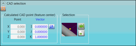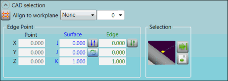
The options in the CAD selection group display the CAD coordinates for a Point feature and enable you to perform CAD-related functions.
Feature Options
The following graphics show the options for each feature.
AA feature:

CAD selection group for AA feature
AC feature:

CAD selection group for AC feature
Descriptions
The following table describes the options.
For descriptions of the icons that appear in this group, see "Using the Icons".
Item |
Description |
Align to workplane list (AC feature) |
Select the workplane. |
Drop-down list (AC feature) |
Type or select the CAD cut-off distance from the click point. A value of "0" indicates that the distance is unlimited. |
Calculated CAD Point (feature center) area (AA feature) |
X, Y, and Z Point boxes: These boxes display the calculated point locations on the CAD model. I, J, and K Vector boxes (AA feature): These boxes display the calculated vector locations on the CAD model. |
Edge Point area (AC feature) |
X, Y, and Z Point boxes: These boxes display the X, Y, and Z nominal for the feature's location. I, J, and K Surface boxes (AC feature): These boxes display the feature's surface locations. Edge boxes (AC feature): These boxes display the calculated approach direction (vector) for the edge hit or for the points. |
Selection area (all features) |
This image displays the navigation path. |
More: