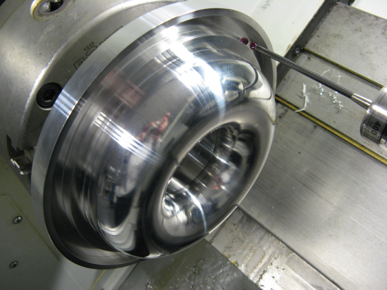
An example of a measurement with the 2d Vector Calibration invoked is to measure profiles around the Toroid (pictured below). It is also used for calibration.
Measurement of a Torus Feature
In this case, a separate measurement routine is created and the CAD model of the toroid is used.
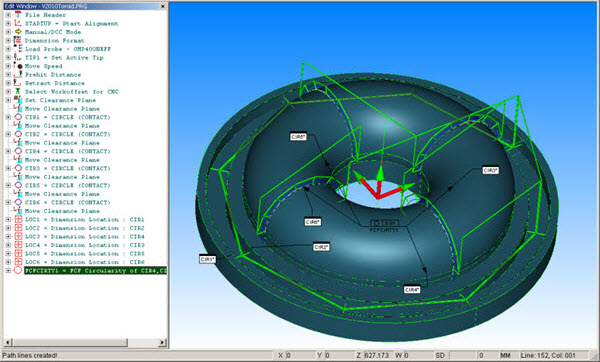
PC-DMIS Measurement Routine and CAD Model for Torus
The journal file produced is shown below.
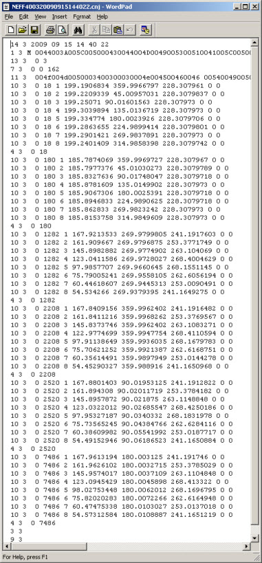
Torus Journal File
When calibrated without the use of 2d Vector Calibration, the Circularity of the four profiles measured are imperfect as shown graphically below.

Torus Circularity Profile with no 2d Vector Compensation
Refer to the caveat mentioned in the calibration section when you run journal files to switch between 2d Vector Calibration and non-2d Vector Calibrations.
When using 2d Vector Calibration, the Circularity deviation of all four profiles reduces from 119 microns to 5 microns as shown below.

Torus Circularity Profile with 2d Vector Compensation