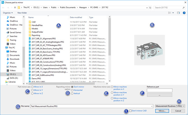
The Mirror command (File | Operations | Mirror) lets you create a mirror image copy in the X, Y, or Z axis of a measurement routine. The command opens the Choose part to mirror dialog box.
Choose part to mirror dialog box
You can only mirror measurement routine (.prg) and CAD files made in valid versions of PC-DMIS. For this version of PC-DMIS, if you attempt to mirror either of these file types created before PC-DMIS version 2015.1, PC-DMIS shows an error message.
Example error message when you try to mirror an invalid measurement routine file:
X Mirrored Copy of <measurement routine file> (Schema: 1215).
Serialization error
This version of PC-DMIS can only read measurement routines created in version 2015.1 up to the version you are running.
This measurement routine was created in a version before 2015.1.
Where <measurement routine file> is the name and location of the file you are trying to open.
The following description describes the items available for selection on the dialog box:
Measurement Routines - This area displays the available measurement routines in the current directory.
Preview - This area shows the CAD image for the last view of your part in the Graphic Display window (without labels). If your part doesn't have any CAD data, the image displays measured geometry. This area only shows images for .prg files.
Part mirror axis - This area defines the axis in which you want to mirror the measurement routine:
Mirror in X - This option mirrors the part in the X axis.
Mirror in Y - This option mirrors the part in the Y axis.
Mirror in Z - This option mirrors the part in the Z axis.
Reporting mirror option - This area defines how PC-DMIS should mirror CAD images in reports:
Don't mirror - This option does not mirror at all.
Horizontal - This option mirrors CAD images horizontally.
Vertical - This option mirrors CAD images vertically.
This area affects reporting objects, such as CadReportObjects, CadImageObjects, Analysis objects, and SectionCutObjects, as well as any defined viewsets in the measurement routine.
Machine mirror axis - This area defines the orientation of the mirrored part on the virtual machine:
Mirror machine position in X - This option mirrors the virtual machine's X axis.
Mirror machine position in Y - This option mirrors the virtual machine's Y axis.
Mirror machine position in Z - This option mirrors the virtual machine's Z axis.
PC-DMIS mirrors the part at the same location as the original part. You can use the Machine mirror axis area to define the orientation of the mirrored part on the virtual machine. You only need to shift the part on the machine to the place it should get measured.
For a description of how these options position your part, consider this diagram:
1 - The machine's origin
 - Original
part
- Original
part
 - Part
mirrored in Y with mirror machine position in Y
- Part
mirrored in Y with mirror machine position in Y
 - Part
mirrored in Y with mirror machine position in X
- Part
mirrored in Y with mirror machine position in X
 (Maximize your help
viewer)
(Maximize your help
viewer)
Reference part - This box pulls out any quick fixture alignment data from the reference part and uses that information in the mirroring operation.
If you use this area to define a reference part, then PC-DMIS does not use the Machine mirror axis area. Instead, the location and orientation of the mirrored part are loaded from the existing (and already mirrored) reference measurement routine.
This option is especially useful if you have multiple measurement routines that belong to the same physical part and need to get mirrored. In this case, you would only need to define the location and orientation of the mirrored part in the first mirrored measurement routine. You could then select the first mirrored measurement routine as the reference part to mirror other measurement routines.
File name - This box defines the measurement routine to mirror.
This file type list filters the display of the current directory to only show measurement routine files (.PRG).
Don't mirror CAD - This check box determines whether the resulting CAD is mirrored. If you select this check box, the resulting CAD is not mirrored. The check box is initially cleared when you first start PC-DMIS. Afterward, this check box retains the state of what was applied in the last mirroring.
You can use the PC-DMIS Settings Editor to change the DoNotMirrorCAD entry's value in the Option section.
To Mirror a Measurement Routine:
If you use an infinite wrist in the measurement routine, you should first set the AlternateTipMirror entry to TRUE. This entry is in the USER_Option section of the PC-DMIS Settings Editor. This entry helps PC-DMIS choose the correct AB angle in cases where the probe head offers more than one possible combination of AB angles to produce the mirrored tip vector.
Select File | Operations | Mirror to open the Choose part to mirror dialog box.
Select the measurement routine file to mirror.
From the Part mirror axis area, select the axis in which you want to mirror.
From the Reporting mirror option area, choose how you want to mirror CAD images in reports.
From the Machine mirror axis area, choose how you want to position the mirrored part on a virtual machine displayed in the Graphic Display window.
If you have an already mirrored reference part, use the Browse button in the Reference part area to select that part. This box pulls out any quick fixture alignment data from the reference part and uses that information in the mirroring operation.
Click the Mirror button to open the Save mirrored part as dialog box with the file name of the measurement routine that you selected to mirror.
Navigate to the directory where you want to save the measurement routine and click the Save button. PC-DMIS mirrors the measurement routine and saves it in that directory. Note that it may take a little while to copy the necessary files.
PC-DMIS also attempts to mirror your probe's AB tip angles. If your probe does not have the exact mirrored tip angles already defined and calibrated, PC-DMIS may choose the closest calibrated tip angles. It chooses closely-calibrated tip angles if the calibrated tip angles exist and are within the wrist angle amount specified in the Wrist warning delta box on the Part/Machine tab of the Setup Options dialog box. If no closely-calibrated AB tip angles exist, then PC-DMIS creates perfectly-mirrored yet non-calibrated AB tip angles. See the "Setup Options: Part/Machine tab" topic in the "Setting Your Preferences" chapter.