Distance Target area
Distance to target check
box
When you select the Distance to target check
box, and the Display distance to closest CAD
check box is not checked, PC-DMIS displays the distance of the probe to
the target point depending on the Distance to
setting. Otherwise, PC-DMIS always displays the distance to the closest
CAD.
The probe's position is displayed in the active coordinate system. Manually drive the probe to the keyed in location. When the target point is reached, the Probe Readouts window will display 0,0,0.
A red line also appears on the Graphic Display window from the probe tip to the target, indicating the next feature to measure.
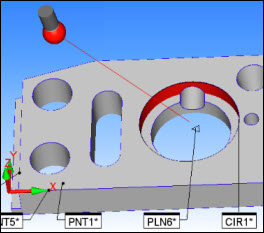
Red Line Pointing to the center of the PLN6 Feature
The target is based on the combination of options specified in the Distance to and Target areas of the dialog box. See a description of these options below and in the "Description of Target for T Value" topic.
With Auto Zoom check box
When you select both the Distance to Target check
box and With Auto Zoom check box, PC-DMIS also
displays the distance of the probe to the target point. The probe’s position
is displayed in the active coordinate system. As the probe is manually
driven to the keyed in location, PC-DMIS makes the target point the center
of the screen and zooms in on the point in the Graphic Display window.
Distance area
This area contains these two option buttons to further define the target:
Executing feature defines the target as the next executing feature.
Closest feature defines the target as the feature closest to the probe.
You can determine the exact location on the target feature (either the centroid or the closest surface/edge point) by selecting the desired option from the Target area.
Target area
This area contains two option buttons to determine the exact target location
to use:
Surface/Edge defines the target as either the closest point on the feature or the next expected point based on what you selected from the Distance area:
If you selected Closest feature, the target is the closest point on the feature.
If you selected Executing feature, the target is the next expected point to take on the feature.
As shown in the above image, for example, while measuring the circle (CIR1), the Surface/Edge option causes the Probe Readouts window to show the distance to the actual target point at location A.
Centroid calculates the distance to the feature's centroid.
As shown in the above image, for example, while measuring the circle (CIR1), the Centroid option causes the Probe Readouts window to show the distance to the feature's centroid at location B, instead of the actual target point.
Vector calculates the distance from the probe's center to the nearest point on the feature's vector.
Display distance to closest CAD
check box
Marking this check box has several effects. When marked, the target becomes
the closest point on the nearest CAD surface. The red line connects the
probe tip to this target.
Also, PC-DMIS displays a ‘T’ (CAD) value, or total deviation value, in the Probe Readouts window. See the "Description of Target for T Value" topic for information on exactly what the distance is used for each feature's T value.
This setting overrules the Distance to Target setting during execution.
Apply dimension color check
box
This check box changes the colors of the deviation values (Distance to
Target values) to match the out of tolerance dimension colors.
Closest CAD tolerance field
This is the field to enter the tolerance (in current units), which is used
to determine the maximum distance the software tries to locate the surface
to compare the current probe position to. Beyond this distance, no distance
to CAD will be returned.
More: