![]()
Parameter Settings dialog box - Clearance Plane tab
The Clearance Plane tab provides the means to define and add clearance planes. Clearance planes, in essence, create an envelope around a part. The probe stays on this envelope when it moves from one feature to another.
PC-DMIS moves the probe out from the part at a predetermined distance, relative to the coordinate system in which it was defined.
After the last hit on the feature is measured, the probe stays at probe depth until called to the next feature. This can help reduce routine creation time because you don't have to define as many intermediate moves. In addition, properly-defined clearance planes can help protect your probe from accidental collisions with the part.
A sample part with an imaginary envelope from clearance planes
To use clearance planes:
Access the Parameter Settings dialog box (Edit | Preferences | Parameters) and then select the Clearance Plane tab.
Select the clearance plane through the Active plane and Pass through plane areas, and specify the clearance distances using the respective Value boxes.
Click OK to finish defining the clearance plane. PC-DMIS inserts a CLEARP command containing the clearance plane information into the Edit window. The finished command looks something like this:
CLEARP/ACTIVE_PLANE, n, PASS_THROUGH_PLANE, n,TOG1
ACTIVE_PLANE and PASS_THROUGH_PLANE refer to the axes selected.
n refers to the offset distances specified.
TOG1 is an ON/OFF toggle field that determines whether the clearance plane is active and automatically used for newly-created Measured and Auto features.
You can then insert MOVE/CLEARPLANE commands into your measurement routine. A MOVE/CLEARPLANE command does not in itself create motion to move the probe to the clearance plane. Rather, when PC-DMIS encounters a MOVE/CLEARPLANE command during execution, that command essentially gives permission to move to the predefined clearance plane on the next move, measure, tip selection, or Auto feature command. When one of those motion commands is about to be executed, the probe moves to the specified distance away from the selected active plane.
If a new CLEARP command is defined, the very next MOVE/CLEARPLANE moves first to the old clearance plane, then to the Pass Through plane, and then to the new clearance plane.
To display the current clearance plane as a translucent
image in the Graphic Display window, from the Graphic
Items toolbar, select the Show Clearance
Plane icon (![]() ). For
more information, see "Viewing
Clearance Planes" in the "Editing
the CAD Display" chapter.
). For
more information, see "Viewing
Clearance Planes" in the "Editing
the CAD Display" chapter.
Active Plane Area
The Active Plane area defines the plane (or axis) in which features lie when they are measured. The Value box defines the clearance plane as an offset distance in the current units of measurement away from the specified plane. To define a clearance plane, select the plane from the Axis list and then enter a new value in the Value box.
Pass Through Plane Area
The Pass Through Plane defines a clearance plane that the probe moves to and then passes through to get to the next active clearance plane after a probe's TIP command. The new CLEARP definition command must immediately follow the TIP command to properly define the pass through plane. When PC-DMIS encounters the next MOVE/CLEARPLANE command, it moves to the pass through plane and remains at that offset distance until it reaches the next active clearance plane.
If you add additional moves or a loadprobe command before a tip change command, PC-DMIS deactivates the pass through plane.
When you make adjustments to commands in your measurement routine, be sure to review the path lines. This allows you to see the effect your changes make without having to run the measurement routine.
Clearance Plane Active (ON) Check Box

If you select the Clearance planes active (ON) check box, PC-DMIS will automatically insert a MOVE/CLEARPLANE command before any Measured Features or Auto features inserted into the Edit window from that point on.
Notes on Clearance Planes
Be aware of the sign of a clearance plane when entering its distance value. The sign must correspond to the positive or negative end of the normal axis defining the plane. For example, to define a top clearance plane, enter a positive value, and to define a bottom clearance plane, enter a negative value.
Movement from one clearance plane to another affects the position of the probe. Make sure that the set clearance plane is sufficient to clear the part.
A clearance plane is defined relative to the current coordinate system and part origin. Therefore, you must be careful when you define a clearance plane to ensure adequate clearance around the part.
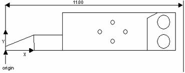
Clearance Plane example
Using the above drawing, suppose your part is ten inches long, and it is lined up close to the machine axes with the X origin at the bottom left-hand corner. You can set a one-inch clearance from the right side of the part by setting the XPLUS clearance plane to 11 inches.
Always define clearance planes relative to the current coordinate system. When you create a new coordinate system, the clearance planes still relate to the first alignment. If you wish to associate the clearance planes with the new coordinate system, they must be redefined.
Clearance planes are not used when taking sample hits. It is therefore important when measuring pins to set the spacer value to a distance that will allow the probe to move around the pin.
For a clearance plane example, see "Clearance Plane Example".