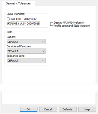
Setup Options dialog box-Geometric Tolerances tab
The Geometric Tolerances tab controls several defaults for the creation of new geometric tolerance commands. For more information on geometric tolerance commands, see the "Using Geometric Tolerances" chapter.
GD&T Standard - This area shows the available standards that you can set as the default standard that you want new geometric tolerance commands to use. When you create a new geometric tolerance command, or access the Geometric Tolerance dialog box, PC-DMIS automatically selects the standard that you set here (ASME Y14.5 or ISO 1101).
Math - As discussed in the "Using Geometric Tolerances" chapter, geometric tolerance commands have three kinds of math options:
Datum math options
Considered feature math options
Tolerance zone math options
This Math area lets you define what math options you want PC-DMIS to use for new geometric tolerance commands. You can change the math options in individual geometric tolerance commands, and it does not affect future geometric tolerances that you create, nor does it affect what you set here.
For information on how to choose the math options for your application, see the "Using Geometric Tolerances" chapter.
Profiles display MAX/MIN values in Profile command (Edit Window) - This check box defines whether PC-DMIS displays the minimum and maximum deviation values in profile tolerance commands inside the Edit window.
If you clear this check box, geometric tolerance commands that represent profile tolerances display a single measured value. This value is based on the single actual value defined by the GD&T standard you selected.
If you select this check box, profile tolerances show the minimum and maximum deviation values instead of the single measured value.