To set up your system, select Edit | Preferences | Temperature Compensation Setup.
To set up temperature compensation for your system as shown in this topic, you need to start PC-DMIS as an administrator. In addition, the value for the UseTemperatureCompensationV2 entry must be True.
Hexagon Systems
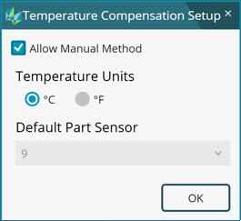
For a machine that is connected to a Hexagon controller, the following options appear in the Temperature Compensation Setup dialog box:
Hexagon system
Allow Manual Method check box:
In special cases, if you would like to manually enter the part temperature, select this check box. Both the automatic and manual methods of temperature compensation become available.
If you clear this check box, only the automatic method of temperature compensation becomes available in the Temperature Compensation dialog box. By default, the check box is cleared. Hexagon recommends use of only the automatic method where available.
Temperature Units - Select degrees Celsius or degrees Fahrenheit.
Default Part Sensor list - Most machines are supplied with one part temperature sensor. This list displays the sensor number with which it is connected to the controller when the machine is online.
Some machines have multiple part temperature sensors. If your system is configured with multiple sensors, multiple sensor numbers appear in this list.
Select a sensor number that you want to designate as the default number. The advantage of using a default sensor number is portability of the measurement routine to another system with a different default sensor number.
If PC-DMIS is connected to a Leica Tracker device, the default part sensor displays as Tracker.
OK button - To save your settings, click OK.
Non-Hexagon Systems
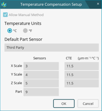
For a machine that is connected to a non-Hexagon controller, the following options appear in the Temperature Compensation Setup dialog box:
Non-Hexagon system
Allow Manual Method check box - It may or may not be possible for PC-DMIS to get the temperature of axes and parts from the controller. When PC-DMIS cannot automatically read the temperatures, the only temperature compensation option is the manual entry of temperatures. This check box is selected by default. You must enter the CTE values for the scale of each axis to compensate for temperature of scales.
You need to enter the temperature of the X scale, Y scale, Z scale, and part at the time of measurement routine execution.
In some cases, it may be possible for PC-DMIS to read the temperature from the controller. In these cases, enter the sensor numbers and CTE values for the scale of each axis and part.
Default Part Sensor list - This list, and the Part Sensor area in the Temperature Compensation dialog box, display Third Party.
OK button - To save your settings, click OK.
Changeable or On-Head Part Temperature Sensor
If PC-DMIS determines that a changeable or on-head temperature sensor is mounted on the probe head, it displays that information in the Default Part Sensor area of the dialog box:
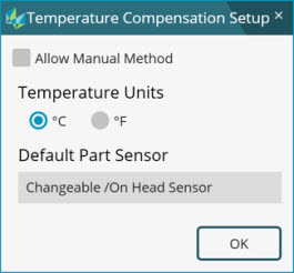
Changeable or on-head sensor
For more information on changeable or on-head sensors, see "Temperature Compensation".
PC-DMIS does not support a changeable or on-head part temperature sensor and a magnetic sensor on the same machine.
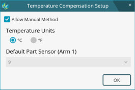
Temperature Compensation with a Multiple Arm CMM
If PC-DMIS is connected to a multiple arm CMM, the default part sensor is one of the part sensors attached to Arm 1. Multiple Arm mode allows the use of part sensors attached to Arm 1 only.
Multiple arm
For a multiple arm CMM, note the following:
Part sensors attached to Arm 1 can only be used to measure the temperature of the part.
Each arm compensates for its own axis. PC-DMIS compensates for the part.
You must ensure that the arms are synchronized before and after temperature compensation. To synchronize the arms, insert MOVE/SYNC commands before and after the TEMPCOMP command.
For more information about multiple arms, see the "Using Multiple Arm Mode" chapter.