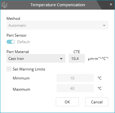
To compensate the measurement for a temperature other than 20 °C as required by ISO-1, select Insert | Parameter Change | Temperature Compensation. The following dialog box appears:
Temperature Compensation dialog box
Method list - From the list, select the temperature compensation method:
Automatic - The automatic method is the default method. It is available for most machines that are connected to a Hexagon controller. These controllers can measure the temperature using a sensor that is mounted on scales and has one or more sensors that can be attached to a part.
If you select this method, PC-DMIS reads the temperatures from the controller. You do not need to enter any temperatures.
Manual - Third-party equipment (non-Hexagon controllers) may not support the automatic method of temperature measurement. For these controllers, only the manual method is available. For this method, you measure and enter the temperature at the time of measurement routine execution.
The manual method is available if the Allow Manual method check box is selected in the Temperature compensation setup dialog box.
If you select this method, the Manual Temperature dialog box appears during measurement routine execution:
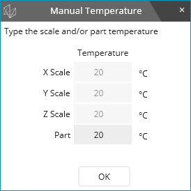
Manual Temperature dialog box
For a Hexagon CMM, PC-DMIS reads and enters the X scale, Y scale, and Z scale temperatures from the controller. You cannot change the temperatures.
You must use a custom sensor to measure the part temperature. Enter the temperature in the Part box.
If the controller does not support a temperature sensor, you must enter the X scale, Y scale, Z scale, and part temperatures.
To continue with measurement routine execution, click OK.
If you are using a Leica Tracker device, select the appropriate temperature compensation method:
If your Tracker device is equipped with a part temperature sensor that can read the part temperature, you can select either the automatic or manual compensation method. If you select the automatic method, PC-DMIS reads the temperature as measured by the Tracker’s part temperature sensor. Ensure that the part temperature sensor is connected to your Tracker and is in contact with the part during measurement.
If your Tracker device is not equipped with a part temperature sensor, only the manual compensation method is possible. During measurement routine execution, you will need to enter the current part temperature in the Part box in the Manual Temperature dialog box. You can use any external device to measure the part temperature.
Part Sensor - The option that appears in this area depends on the type of part sensor:
One part temperature sensor - Usually, a controller is equipped with only one part sensor. This sensor appears in the dialog box as Default. You cannot cancel the selection of this sensor.
Multiple part temperature sensors - Some controllers support multiple part sensors. If your controller is equipped with multiple part sensors, each part sensor number appears in this area. For example:
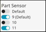
Multiple part sensors
Select the sensor or sensors that are connected to the part being measured. Ensure that you select the correct sensor number. If you select multiple sensors, PC-DMIS uses the average temperature for thermal compensation.
External temperature sensor - You may need to use an external sensor to measure the part temperature. In this case, you can use a variable to determine the temperature of a part. This sensor appears in this area as follows:
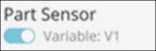
For more information, see "Variable for Part Temperature in Temperature Compensation Command".
Changeable or on-head part temperature sensor - The Hexagon FDC and Leitz controllers on fixed-head CMMs can be equipped with a changeable or on-head part sensor that is mounted on the probe head. The controller can also be equipped with a probe-like sensor that can measure the part temperature by probing a point on the part. These sensors appear in this area as follows:
Changeable or on-head part sensor
PC-DMIS can determine whether the part sensor on the Leitz controller is a changeable or an on-head part sensor. For the FDC controller, the UseChangeableTemperatureProbes entry in the PC-DMIS Settings Editor must be set to True.
For information about creating and using a changeable temperature probe file, see "Working with Temperature Sensors" in the PC-DMIS CMM documentation.
For a machine that is connected to a non-Hexagon controller, the sensor appears as Third Party. For more information, see "Temperature Compensation Setup".
Part Material list - From the list, select the material of the part. The material's coefficient of thermal expansion (CTE) appears in the CTE box.
Part materials and coefficients are stored in the MaterialCoefficients.xml file. You can use a text editor or the Material Coefficients Editor to modify this file. For complete information, see "Editing Part Materials and Coefficients".
CTE (Coefficient of Thermal Expansion) - This is a unique value. When you select a part material, the coefficient value appears in the CTE box. You cannot modify this value in the dialog box, but you can change it in the Edit window. When you modify the CTE value in the Edit window and press Tab, PC-DMIS attempts to find a matching material. It searches through the available materials in the MaterialCoefficients.xml file. It then displays the material that corresponds to the typed value. If it cannot find a corresponding material, PC-DMIS sets the MATERIAL field in the Edit window to "Custom Material". When you next open the Temperature Compensation dialog box, you will see "Custom Material" in the Part Material list. You can select any other material from the list.
The CTE field in the Edit window also supports variables. If you use a variable in this field, PC-DMIS uses the current variable value during execution. If you type a variable name for the CTE field in the Edit window, the material appears as "Variable". If you press F9 to edit this command, the material appears as "Variable", and the CTE is the current value of the variable. You cannot select another material in the Part Material list. To change the material, you need to remove the variable name from the CTE field in the Edit window.
The CTE value's units is in micron per meter per degree C (or µm·m-1·°C-1). Before version 2017 R2, this was in meter per degree C. This means, for example, that a previous value of 0.0000115 now appears as 11.5.
The CTE value must be a unique value. If you have two or more materials that have the same CTE value, you must enter them on the same row in the Material Coefficients Editor separated by a forward slash.
For example, if Material1 has the same CTE value as Material2, you must enter "Material1/Material2" in the Materials column. In the corresponding Coefficients column, you would enter the CTE value.
For information on how to use the Material Coefficients Editor, see the "Editing Part Materials and Coefficients" topic.
Based on the CTE value, PC-DMIS will search for the corresponding material in the MaterialCoefficients.xml file.
Set Warning Limits check box - The TEMPCOMP command displays a warning if the temperature of the X scale, Y scale, Z scale, or part is outside of the limit.
The TEMPCOMP command also supports the "Temperature Outside Limits" error type.
You can use the options in the On Error dialog box to control the measurement only if the specified temperature conditions are met. For detailed information about setting up the options in the dialog box, see "Branching on an Error".
Minimum and Maximum boxes - These boxes display temperatures as follows:
If you select the Set Warning Limits check box, PC-DMIS sets the suggested minimum temperature to 18 °C and the maximum temperature to 22 °C. You can modify the values.
If you clear the Set Warning Limits check box, the minimum temperature is set to 10 °C and the maximum temperature is set to 40 °C. You cannot modify the values.
You can input temperature values between 50°F (10°C) and 104°F (40°C). You can also use variables in the Edit window for the MINIMUM and MAXIMUM fields. Ensure that the Minimum value is less than the Maximum value.
When you click OK, PC-DMIS inserts a TEMPCOMP/METHOD command into the measurement routine.

Command Mode
Normally, a measurement routine only uses one TEMPCOMP command. The TEMPCOMP command should be placed near the top of the measurement routine prior to any measurements. When you execute the measurement routine, it executes according to the various input parameters.