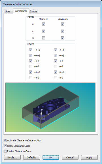
Use the Constraints tab of the ClearanceCube Definition dialog box (Operation | Graphic Display Window | ClearanceCube) to specify which of the six faces and 12 edges you want to use for planned motion.

ClearanceCube Definition dialog box - Constraints tab
Faces area - The check boxes in this area indicate which of the six faces you want to use for planned motion. If a face is cleared it is not used. The minimum check boxes correspond to the XMINUS, YMINUS, and ZMINUS faces. The maximum check boxes correspond to the XPLUS, YPLUS, and ZPLUS faces.
Unless you have a MACHINE command for a horizontal arm machine, PC-DMIS assumes that you are using a vertical arm machine, and clears the Z Minimum check box. It assumes your part is sitting on the vertical machine's table, and that motion does not occur in the ZMINUS direction. On a horizontal arm machine, the Y Minimum check box is cleared, so that motion does not occur in the YMINUS direction.
You can, of course, mark any check box you wish. For example, if you're using a vertical machine, and the part is held above the table surface by a fixture, then you may want to mark the Z Minimum check box so that motion occurs in that direction as well.
Edges area - The check boxes
in this area indicate which of the 12 edges you want to use for planned
motion. If an edge is cleared, it is not used. This is helpful for those
cases where you may have a face available for planned motion, but you
may not have an edge available due to a part clamp or some other obstruction.
By default, PC-DMIS clears the four edges corresponding to any cleared
faces. Each of the edge check boxes lists two axes as part of its label.
These axes correspond to the surfaces making up that edge. For example,
+X +Y means that edge touches both the X+ surface and the Y+ surface.

Preview Area - The CAD preview shows the effects of your edges and faces modifications. Clearing any check boxes draws those edges and faces in a cyan colored rectangle or line, indicating that motion is not be applied for those elements of the ClearanceCube.
Activate ClearanceCube motion - This is already described in the "(Simple) ClearanceCube Definition" topic.
Show ClearanceCube - This is already described in the "(Simple) ClearanceCube Definition" topic.
Resize ClearanceCube - This is already described in the "(Simple) ClearanceCube Definition" topic.
Defaults - This button allows you to reset the Constraints tab to the default settings based on the current measurement routine.
Simple - This button sets the dialog box back to its initial simplified state.