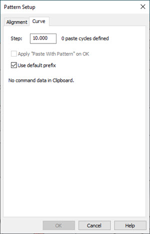
The Curve tab on the Pattern Setup dialog box allows you to set up a pattern for a part with one or more edge segments around a part surface. These segments can be straight edges or curved edges. With this tab open, you can click on your CAD model to select an edge. To select multiple edges, press Ctrl and click on the part to add a new edge. You may find this tab helpful to measure a profile comprised of several points pasted around a part's surface.
To remove a selected edge, hover over it and click on it again. To remove the last selected edge, click the blue ball.
When you paste the pattern, the copied commands are pasted at the defined offset value along the selected edges.

Step
This defines the offset distance between patterned features. The default is 10. The units are based on the measurement routine units which get converted accordingly. The Step value must be greater than 0 (zero).
When you type a value in the Step box, you need to tab out of the box or click outside the box to set the value. PC-DMIS updates the text to the right of the Step box based on the value you typed.
Apply "Paste With Pattern" on OK
You can manually select the Paste With Pattern menu option if you like, or you can use this check box. This check box applies the Paste With Pattern operation behind the scenes automatically when you click OK.
Use default prefix
The Use default prefix check box specifies whether PC-DMIS uses a default ID prefix when you use the Paste With Pattern menu item to paste features.
If you select this check box, the Paste With Pattern menu item uses the default ID prefix when you paste new features.
If you clear this check box, the Paste With Pattern menu item uses each feature ID as the base feature name and adds an incremental and numerical suffix.
If you don't use a default prefix when you paste many lines, the processing time is longer because each feature ID represents a new pattern.
Once you click the OK button, you can press the Esc key to stop the Paste With Pattern process. Features that have already been pasted remain, but PC-DMIS does not paste any new features.
More: