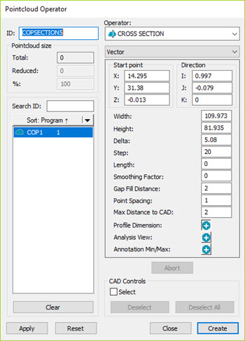
Pointcloud Operator dialog box - Cross Section Operator
The CROSS SECTION operation generates a subset of polylines determined by the defined intersection of a set of parallel planes with the COP or Mesh object. The set of planes is defined by the start point, direction vector, step distance between the planes, and length. The number of planes is determined by the Step distance divided into the Length plus one.
The CROSS SECTION operator can be evaluated by the profile dimension.
To apply the CROSS SECTION operation to a pointcloud,
click Cross Section Pointcloud ( ) on the Pointcloud
toolbar, or select Insert | Pointcloud | Cross Section.
) on the Pointcloud
toolbar, or select Insert | Pointcloud | Cross Section.
From the Pointcloud or QuickCloud toolbar, click the 2D
Section Slide Show button  to display cross sections in the 2D view. For details, see the "Cross
Section Slide Show" section of the "Show
and Hide Cross Section Polylines" topic.
to display cross sections in the 2D view. For details, see the "Cross
Section Slide Show" section of the "Show
and Hide Cross Section Polylines" topic.
The drop-down list under the Operator list contains these options: Vector, Axis, Curve, and 2 Points. For details on how the Curve function works, see the "Creating a Cross Section along a Curve" topic. For details on the 2 Points option, see the "Creating a Cross Section between 2 Points" topic.
The CROSS SECTION operator uses the following options:
Start point: This value indicates the coordinates of a point that belongs to the first plane that cuts the pointcloud.
The software displays the start point as a blue ball in the Graphic Display window. You can use the ball as a handle to drag to a new location. You define the start point by your first click in the Graphic Display window. In the actual Edit window command, the start point value is held in the START PT parameter.
Direction (applies only to the Vector and 2 Points option): This value indicates the direction of the normal vector. You define the direction by your second click in the Graphic Display window. In the actual Edit window command, the Direction value is held in the NORMAL parameter.
Axis (applies only to the Axis option): Use this option to create a cross section along the X, Y, or Z axis. Select the desired axis (the default is X), set a start point in the Graphic Display window, and set an end point. The section plane cuts the part at a given step value over the length of the cross section.
Width: This value indicates the width of the section under consideration. If the value is 0, the system calculates the value as the CAD and COP bounding box value.
Height: This value indicates the height of the section under consideration. If the value is 0, the system calculates the value as the CAD and COP bounding box value.
Delta: This value indicates the maximum distance from the plane for a point to be considered part of the cross section. In the actual Edit window command, the Delta value is held in the TOLERANCE parameter. The Delta property is only available when a COP object is selected.
Step: This value indicates the distance between the planes. In the actual Edit window command, the step value is held in the INCREMENT parameter.
If the value in the Step box is greater than the value in the Length box, then only one section cut is created at the start point.
Length: This value indicates the maximum distance between the first and last plane. The software displays the length value in the Length parameter of the dialog box. PC-DMIS displays it as a purple line in the Graphic Display window.
Smoothing Factor: You can use the Smoothing Factor to apply a Least Square fit with a smoothing constraint to an ordered set of points. There is a trade-off when using the Smoothing Factor, since, as the roughness of the spline is smoothed, the points move from their original position. Consequently, you should use caution when you apply the smoothing factor since it moves or changes the data. This option may be useful for smoothing points that you consider to be "noise".
There is no upper limit to the Smoothing Factor value. However, the more you increase this value, the less effect it has on your data until any noticeable change is seen. When you use a very large smoothing factor, changes occur to the original shape of the measured cross section polyline.
A value of 0 (zero) applies a very small internal smoothing factor.
You should test the Smoothing Factor option with a starting value between 0.1 and 0.25. Then, depending on the result, increase the value to 0.5, 1 or 2 and re-test until you achieve the desired result.
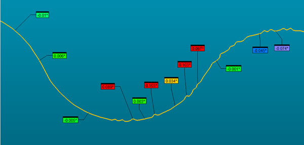
Example with the Smoothing Factor set to 0 (zero)
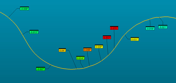
Example with the Smoothing Factor set to 0.5
Gap Fill Distance: This value defines the maximum gap distance along the yellow measured polylines of a cross section. If gaps equal to or smaller than this value appear, PC-DMIS fills in the gaps with calculated points. You can also set this value in the PC-DMIS Settings Editor. For details, see the "CrossSectionMaximumEmptyLength" topic in the PC-DMIS Settings Editor documentation.
Point Spacing: This value is used only when the CrossSectionCopCadCrossSectionDrivenByCad entry is set to 1 (True). This value is the step used along the CAD polylines to look for the best interpolated COP point. For greater accuracy, or if the CAD model is very small, you can set this value to a smaller value.
You can also set this value in the PC-DMIS Settings Editor. For details, see the "CrossSectionCopCadCrossSectionStep" topic in the PC-DMIS Settings Editor documentation.
Max Distance to CAD: This value defines the maximum distance of the pointcloud data relative to the nominal CAD model. The default value is 2 mm. If the scanned part deviates more than the Max Distance to CAD value from the CAD model, the software may not compute the yellow measured cross section. You can adjust this value to account for large deviations of the scanned data relative to the CAD model.
Profile Dimension:
Click the Add button  to create a new profile dimension for each cross section. For details
on Profile Dimension, see "Dimensioning
Profile - Line or Surface" in the "Using
Legacy Dimensions" chapter of the PC-DMIS Core documentation.
to create a new profile dimension for each cross section. For details
on Profile Dimension, see "Dimensioning
Profile - Line or Surface" in the "Using
Legacy Dimensions" chapter of the PC-DMIS Core documentation.
Analysis View: Click the Add button to create the ANALYSISVIEW command in the Edit window. For details on the ANALYSISVIEW command, see "Create Analysis View Command" in the "Inserting Report Commands" chapter in the PC-DMIS Core documentation.
Annotation Min/Max: Click the Add button to create the minimum and maximum values in the form of annotation labels for the active cross section.
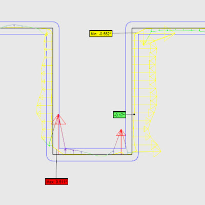
PC-DMIS calculates the minimum and maximum points each time you execute the measurement routine.
CAD Controls: Mark the Select check box to select CAD surfaces in the Graphic Display window. PC-DMIS filters out any cross sections that do not pass through the selected surfaces when you click Create.
For example, if you selected surface A after the start and end points are defined, PC-DMIS only generates cross sections at B and C:
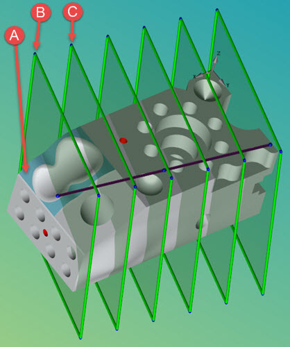
Example of a selected surface (A) limiting the cross sections to only (B) and (C)
Selected surfaces do not affect what you see when you click the View button.
When the cutting planes are visible in the Graphic Display window, you can manipulate them as follows:
To resize the height and width of the cutting planes, drag a plane’s edge handle to a new position.
To rotate the set of planes around their axis, drag a plane’s corner handle to a new position.
To redefine the purple line's START or END definition, drag the first or last purple length line’s blue point handle to a new position. While the direction is changing, the values in the dialog box and the number of planes in the Graphic Display window are updated. In Axis mode, the direction of the planes does not change.
To move the set of planes, drag the purple length line’s middle blue point handle.
When a cross section is created or edited, the cutting planes appear in a transparent view as shown above.
Click Create to:
Insert a COP/OPER,CROSS SECTION command for each plane into the Edit window.
For example:
COPSECTION3=COP/OPER,Cross Section,TOLERANCE=0.05,WIDTH=117.715,HEIGHT=227.086,
START PT = -6.439,60.097,6.276,NORMAL = 0.9684394,-0.2221293,-0.1130655,SIZE=76
REF,COP1,,
The black polylines represent the nominal CAD, the yellow polylines represent the COP polyline.
Insert a label for each plane into the Graphic Display window as shown below:
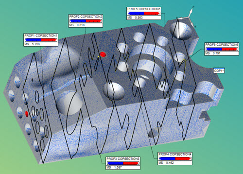
Finished cross sections showing six planes
Defining the Cross Section by Typing Values
Use the Pointcloud Operator dialog box to type the values:
START PT: This value specifies the cross section's starting point using the Start Point X, Y and Z boxes.
NORMAL: This value specifies the cross section's vector using the Direction I, J and K boxes.
WIDTH: This specifies the value of the cross section's width property in the Width box.
HEIGHT: This specifies the value of the cross section's height property in the Height box.
TOLERANCE: This specifies the value PC-DMIS uses to determine the maximum distance from the plane a point must be in order for PC-DMIS to consider it as part of the cross section in the Delta box.
INCREMENT: This specifies the value between cutting planes in the Step box.
LENGTH: This specifies the value between the first and last cutting planes in the Length box.
SMOOTHING TOLERANCE: This specifies the tolerance value to refine the points associated with the generated cross section in the Smoothing Tol box.
Defining the Cross Section by Using the Graphic Display Window
To define some of the cross section parameters, click the CAD model in the Graphic Display window to select the Start Point. A pink line appears. Click a second point on the CAD model to determine the Direction vector and the Length.
Creating a Profile Dimension from the Graphic Display Window
When you double-click a cross section label, PC-DMIS creates a new profile dimension that evaluates the selected cross section.
Measuring a Radius on a Cross Section with the 2D Radius Gage
PC-DMIS provides the 2D Radius Gage to quickly measure the radius on a pointcloud cross section. For details, see "2D Radius Gage Overview".
More:
Creating a Cross Section along a Curve
Creating a Cross Section between 2 Points
Show and Hide Cross Section Polylines