To change a value, right click on the current value for the desired target. If a value says N/A, then that parameter is "not applicable" to the current set.
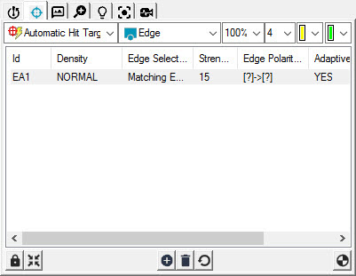
ID: This column displays a unique identifier for the item in the target list. This same ID is used on the tooltip for the target in the Vision tab of the Graphic Display window.
Min/Max Type: For edge point, when either the Min, Max, or Mean option is selected, the target is actually a rectangular region. It has scan directions, and the size of the rectangular area can be changed. Multiple edge scans are created parallel to the target's scan direction for edge detection within the defined rectangle region. One point is detected for each edge scan, and the result is calculated based on the selected option.
The available options are:
None: Returns a normal edge point with a single line target going through the edge. Only a single point is detected.
Min: Returns the point that is the minimum distance from the scan point along the scan direction.
Max: Returns the point that is the maximum distance from the scan point along the scan direction.
Mean: Returns the average of all the detected points along the scan direction.
Density: This column shows the hit density type for the current target. Available density types include:
The Density option is not available for Edge Point or Surface Point scans.
None: Does not return points. Use this type when excluding a region on the target. Excluded regions are indicated with a crosshatch pattern on top of the feature.
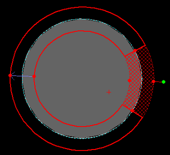
A target with an excluded region shown by the crosshatch pattern
Low: Returns a minimal number of points (one point for every 10 pixels). Use this density type if your feature form doesn’t change much in this area, or if it isn’t a critical area of your part.
Normal: Returns the default number of points (one point for every 4 pixels) for that feature type.
High: Returns the maximum number of points (one point per pixel). Use this density type if your feature form changes drastically in this area, or if it is considered a critical area of your part.
Under Scan: This defines (in current units) the under-scan distance applied to non-blending areas within a target (for example, a corner made from two edges). PC-DMIS Vision doesn't return any points from under-scan areas on a target, and the display indicates the ignored area. PC-DMIS Vision attempts to default the Under Scan value to an appropriate setting.
The Under Scan option is not available for Edge Point or Surface Point scans.
Edge Selection: PC-DMIS Vision attempts to find and use the most appropriate means of detecting an edge. It supports these methods:
Dominant Edge: Often, when using the bottom lamp to illuminate the part, you can get best results by returning the dominant (or strongest) edge.
Nearest Nominal: This method detects the qualified edge closest to the nominal edge. This gives you an easy way to select a non-dominant edge for measurement.
Matching Edge: This method detects the edge whose size and location best matches that of the required feature. This is the default edge detection method. For steps that can be taken to speed up this Edge Selection type, see the "Troubleshooting PC-DMIS Vision" topic.
Specified Edge: This method goes in the currently defined scan direction and picks a specified edge from the detected edges whose strength value exceeds that of the edge strength threshold. The Graphic Display window shows the scan direction using a blue arrow in the target. You can reverse this direction to select edges in a preferred order.
Strength: This shows the edge strength threshold to use during the feature measurement. When looking for an edge, the software ignores edges with an assigned 'strength' below this threshold. You can change the predefined value to a new value with a range of 0-255. The larger the number, the stronger the edge. If PC-DMIS Vision does not return sufficient points on an edge, try reducing this value. If vision returns a number of false edges detected, try increasing this value.
Edge Polarity: This value determines if the edge that is viewed and discovered goes from black to white, white to black, or either. This value can be specified for the following edge types: Dominant Edge, Nearest Nominal, Matching Edge, and Specified Edge.
Setting the Edge Polarity allows edges of a specific polarity to be excluded from the algorithms, providing speed improvement. For example, setting polarity to [|]>[] throws away any edges that are not black to white, as it would for dominant edge.
Hit Target Direction: This value determines the direction that the algorithm uses when determining polarity. For example, if you run across a target in one direction, and edge would be white to black ([ ]>[|]), but in the other direction, the same edge would be black to white ([|]>[ ]). This value is always available for the Specified Edge type. If the polarity is set to something other than any to any [?]>[?], then it also becomes available for Dominant Edge, Nearest Nominal, and Matching Edge.
Specified Edge #: This value shows what edge to use for the Specified Edge detection method recently discussed. You can specify a value of 1-10.
Adaptive Threshold: Set this to YES to deal with variations in illumination. This setting is by default set to YES as it is appropriate in most situations. Having this on is necessary, for example, when your machine has non-uniform illumination, and the feature's learned location may differ from its location within the FOV when executed.
With fixed threshold, it is possible that different edge points are detected, causing measurement error or instability. However, if the part area included in the target band changes due to texture or other noises, those changes could cause the result of the adaptive threshold to be higher than the intended edge’s threshold. The result is that the intended edge is not detected. In this situation, it may be best to set Adaptive Threshold to NO.
SensiLight: This determines whether or not the machine should perform an auto-light adjustment prior to measurement, in an attempt to achieve optimal results. If set to NO, PC-DMIS sets the lighting according to the learned percentage, and the brightness is not adjusted automatically. SensiLight is short for Sensible Lighting.
At execution time, if SensiLight is on, a quick check is made to ensure the illumination is not too dark or too light. If it is, then it auto adjusts the illumination to make it sensible. It then gives the operator the option of saving this new illumination setting so that the next time the feature is measured it uses the new improved settings.
Illumination: This shows the illumination values to use for this target. To change the illumination for a specific target, select the target in the Hit Targets tab, or on the Vision tab of the Graphic Display window, and change the illumination on the Illumination tab. For information on how to do this, see "Probe Toolbox: Illumination tab".