
The CAD Selection method is used to add a feature to your measurement routine. Click the desired CAD element (such as a circle, an edge, a surface and so on) inside the CAD tab of the Graphic Display window. If you want to insert an open Profile 2D, select the series of CAD elements that form the Profile 2D you wish to measure.
The following steps show how to add a circle feature to your measurement routine using the CAD selection method:
Access the Auto Feature toolbar by clicking View | Toolbars | Auto Features from the main menu or right-click in the toolbars area and select it from the list.
Click the Circle button. The Auto Feature dialog box for a circle appears.
Keep the Auto Feature dialog box open and select the CAD tab of the Graphic Display window. Then click once on the edge of the desired circle. Other features may require additional or fewer clicks. See "Required Clicks for Supported Features".

Selecting a circle from the CAD View
Click as close as possible to the CAD element to ensure PC-DMIS does not choose an incorrect element.
PC-DMIS Vision automatically places the nominal data for the feature into the Auto Feature dialog box.
The hit targets are automatically displayed for all features. The resulting CAD window view should look something like the following:
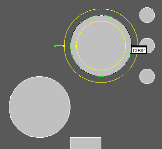
Circle feature with target
Notice that the software selects the desired circle feature and draws a target showing the scanning region band.
Click Create on the Auto Feature dialog box to add the feature to the measurement routine.