Probe Readout window
Most of the information in the Probe Readouts window is the same for all probe types and is already discussed in the "Using the Probe Readouts Window" topic of the "Using Other Windows, Editors, and Tools" chapter in the PC-DMIS Core documentation. However, if you use a vision probe, the following additional readouts appear in the window.
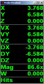
VX / VY / VZ: If you are using a vision probe, the X, Y, and Z values indicate the coordinates of the crosshair at the center of the field of view (FOV). The VX, VY, and VZ values indicate the feature Target or Gage location with respect to the current alignment.
DX / DY / DZ: The DX, DY, and DZ values indicate the difference between the camera and feature position. You must have the Distance to Target option selected in the Probe Readouts Setup dialog box for these values to appear. For more information, see "Setting Up the Probe Readouts Window" in the "Setting your Preferences" chapter in the PC-DMIS Core documentation.
Mag: This value shows the current camera magnification setting. Any changes you make in the Magnification tab are reflected on this line of the Probe Readouts window. See "Probe Toolbox: Magnification tab".
W: Displays the current rotary table axis for a single rotary table.
V: When you use a stacked rotary table, the Probe Readouts window also shows a "V" value for a second rotary axis.
Vision Laser Sensors
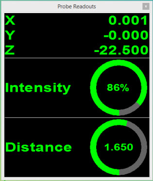
If a vision laser sensor is the active sensor, the Probe Readouts window displays the X, Y, and Z readouts, plus the laser parameters such as Intensity and Distance. For details, see the appropriate laser sensor section in this document.
An example appears below:
More:
Supported Lasers on Vision Systems