From the Edit menu, point to Graphic Display Window, and choose Screen Color. Then from the CAD and Graphic Setup dialog box, click the Wireframe tab.
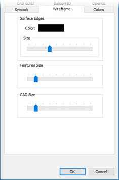
CAD and Graphic Setup dialog box-Wireframe tab
The Wireframe tab of the CAD and Graphic Setup dialog box controls how to draw wireframe elements in the Graphic Display window.
Surface Edges area
You can have PC-DMIS draw bold lines around edges of surfaces. These lines are called "surface edges".
To show or hide the surface edges, from the Graphic
View toolbar, click Surface Edges ( ).
).
This area controls how surface edges appear:
Color - This box opens the Colors dialog box, so that you can define the color of surface edges.
Size - This slider sets the width of surface edges.
This example shows surface edges with thick green lines, instead of the default black lines:

Features Size area
This area contains a slider. This slider sets the width of features that PC-DMIS draws on top of the CAD model in the Graphics window. For example, if you measure a line feature, PC-DMIS draws a line in 3D space at that location on the model. This area modifies drawn items like that.
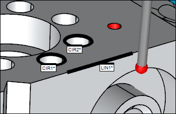
This example shows two circle features and a line feature at a larger width:
CAD Size area
This area contains a slider. This slider sets the width of these items:
CAD curves and CAD surfaces in a wireframe view
Lines that render embedded CAD GD&T objects
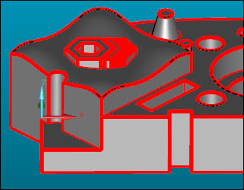
This example shows part of a mixed solid and wireframe CAD model with larger wireframe lines from this setting. (The CAD model's original format already had a red color for the wireframe lines.)