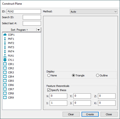
Construct Plane dialog box
There are several methods to use PC-DMIS to construct a plane. The following table lists the various types of constructed planes along with their necessary inputs. Some features may require no inputs, while others may require three or more inputs. In the following table, the term "Any" indicates that the construction can take any type of feature as input for construction. PC-DMIS allows the features to be selected in any order.
CONSTRUCT FEATURE TYPE |
SYMBOL IN EDIT WINDOW |
# OF INPUT FEATURES |
FEATURE #1: |
FEATURE #2: |
FEATURE #3: |
COMMENTS |
Auto Plane |
- |
- |
- |
- |
- |
See "Auto Plane Construction". |
Alignment Plane |
ALIGN |
0 |
- |
- |
- |
Constructs a plane at alignment origin. |
Best Fit Plane |
BF |
At least three inputs are needed. |
- |
- |
- |
Constructs best fit plane using the given inputs. See the Note below for recommended inputs. |
Best Fit with Recomp Plane |
BFRE |
At least three inputs are needed (one must be a point). |
- |
- |
- |
Constructs a best fit plane using the given inputs. See the Note below for recommended inputs. |
Cast Plane |
CAST |
1 |
Any |
- |
- |
Constructs a plane at the centroid of the input feature. |
Primary Datum Plane |
PRIMARY DATUM |
3 or 1 |
Any (one of three) Or if only one input: one feature set, one plane, or one scan |
Any (2 of 3) |
(Any 3 of 3) |
Constructs a plane tangent to the highest available points. |
Mid Plane |
MID |
2 |
Any |
Any |
- |
Constructs a mid plane between the centroids of the inputs. |
Offset Plane |
OFFSET |
3 or 1 |
Any (one of three) Or plane feature if only one input |
Any (2 of 3) |
Any (3 of 3) |
Constructs a plane offset from the input features (or from single plane feature). |
Parallel Plane |
PLTO |
2 |
Any |
Any |
- |
Constructs a plane parallel to the first feature and passing through the second feature. |
Perpendicular Plane |
PRTO |
2 |
Line or Axis Element |
Any |
- |
Constructs a plane perpendicular to the first feature and passing through the second feature. |
Reverse Plane |
REV |
1 |
Plane |
- |
- |
Constructs a plane passing through the input with a reversed vector. |
Translated Plane |
TRANSLATED |
1 |
Plane with point data |
- |
- |
Constructs a plane at an offset from the input plane. |
Extracted Plane |
EXTRACTED_PLANE |
1 |
COP or Mesh |
- |
- |
Constructs an extracted plane from the COP or Mesh object at the specified width and length properties. |
For Best Fit (BF) or Best Fit Recompensate (BFRE) constructions, while you can use any feature type for your input features, BF and BFRE fit types are typically used with point features or point sets (a scan of points, a feature set with points, or an expression that resolves to an array of points).
If you select inappropriate feature types, PC-DMIS displays this message on the Status bar:
"Cannot construct [feature]. Combination of input features not accepted."
To construct a plane, do the following:
Open the Construct Plane dialog box (Insert | Feature | Constructed | Plane).
Use the Method list to select the method type for the constructed plane. The available options are:
Auto Plane
Alignment Plane
Best Fit Plane
Best Fit Recompensate Plane
Cast Plane
Mid Plane
Perpendicular Plane
Parallel Plane
Reverse Plane
Primary Datum Plane
Offset Plane
Translated Plane
Extracted Plane
Use the table above to select the appropriate features from the Feature list for the constructed plane based on the selected method.
Make the necessary changes to other options that become available based on the selected method for the constructed plane. These are described in the topic specific to the method you selected.
From the Display area, select how you want PC-DMIS to display the constructed plane. For details, see the "Using the Display Area" topic in this documentation.
If you want to change the feature theoretical values, select the Feature theoreticals check box and type in the values. For details, see the "Specifying Feature Theoreticals" topic in the PC-DMIS Core documentation.
Click the Create button.
The Edit window command line for a sample plane construction would read:
feature_name=FEAT/PLANE,TOG
THEO/x_cord,y_cord,z_cord,i_vec,j_vec,k_vec
ACTL/x_cord,y_cord,z_cord,i_vec,j_vec,k_vec
CONSTR/TOG2,TOG3,...
If TOG2 = PLANE and TOG3 = BF or BFRE, the command has the following format:
feature_name=FEAT/PLANE,TOG1,TOG6
THEO/x_cord,y_cord,z_cord,i_vec,j_vec,k_vec
ACTL/x_cord,y_cord,z_cord,i_vec,j_vec,k_vec
CONSTR/PLANE,TOG3
OUTLIER_REMOVAL/TOG5,stdDevMultiplier
FILTER/TOG5,WAVELENGTH= cutoffWavelength
The actual Edit report displays in all capital letters.
AUTO is the default method of construction. This option automatically determines the best way to construct a plane using the input feature(s). See "Auto Plane Construction".
TOG1= POLR or CARTESIAN
TOG2 = PLANE
TOG3 = ALIGN / BF / BFRE / CAST / TANGENT / MID / OFFSET / PLTO / PROJ / PRTO / REV / TRANSLATED
TOG5 = ON / OFF
TOG6 = LEAST_SQR / MIN_SEP
stdDevMultiplier = This option is only available for Best Fit and Best Fit Recompensate methods. It determines whether or not a measured point is an outlier. If the point from the plane is further than the standard deviation multiplied by this, then it is an outlier and will be removed if you have selected the Remove Outlier option.
cutoffWavelength = This option is only available for Best Fit and Best Fit Recompensate methods. It controls the amount of data smoothing. The longer the wavelength, the more smoothing there is.
The first three lines that display in the Edit window are the same for constructed planes. The fourth line is slightly different, according to the type of feature being constructed. To switch between the different types of planes, place the cursor on TOG3 and press F7 or F8. (See "Command Mode Keyboard Functions" in the "Using the Edit Window" chapter.)
When two or more features are involved, PC-DMIS automatically determines the necessary order of the input features. This improves the accuracy of the measurement process.
The following subtopics describe the available options for constructing a plane:
More:
Constructing a Plane from an Alignment
Constructing a Best Fit or Best Fit Recompensate Plane
Constructing a Perpendicular Plane
Changing the Direction of a Plane
Constructing a Primary Datum Plane
Constructing a Translated Plane