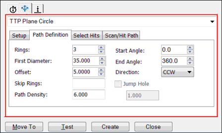
The Path Definition tab for the TTP Plane Circle strategy provides you with options to define a circular scan path. When the scan path is generated, the hit points are also selected based on the selection criteria that is currently specified on the Select Hits tab.
You can view the scan path whenever you update a path definition parameter and then move the cursor away. You can also view the updated scan path in the Graphic Display window.

Sample Path Definition tab
Rings
Type or select the number of rings.
First Diameter
Type the diameter of the first ring.
Offset
Type the distance between two rings.
Skip Rings
Type the ring number or numbers that you want to skip.
To skip rings 2 and 4, type 2,4. To skip rings 2 through 5, type 2-5.
Path Density
Type the number of points per mm that you want to use to create the scan path.
Start Angle
Type or select the start angle, in decimal degrees.
End Angle
Type or select the end angle, in decimal degrees.
Direction
Select CW (clockwise) or CCW (counterclockwise).
Jump Hole
If you select this check box, PC-DMIS generates a break point in the scan path whenever the scan path is over the holes in the CAD surface. Type the required distance from the edge in the box.
If you select the Jump Hole check box, PC-DMIS looks for a break in the surface 360 degrees around every point in the path. If the path is closer than the jump hole distance from the edge, PC-DMIS jumps the path and then removes the path.