Probe Toolbox: Contact Auto Move Properties tab
This tab becomes visible when you have the Auto Feature dialog box open and you enable a contact probe.
The Contact Auto Move Properties tab contains items that allow you to change Auto Move properties for Auto Features that use contact probes.
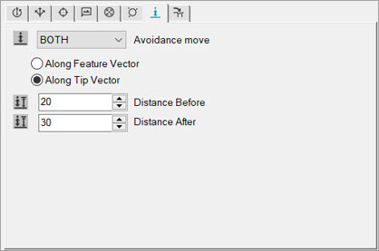
You define the AVOIDANCE MOVE command from the Contact Auto Move Properties tab of the Probe Toolbox. From this tab, you define the type of avoidance move from the Avoidance move list, the approach that you want the tip to take and the amount to move before and after you create the Auto feature.
A useful way of visualizing how these properties affect
the measurement is to display pathways and hits with the Show Hit Targets icon ( ).
).
Auto moves are special moves added to your feature's path lines to help PC-DMIS avoid driving the probe through your feature when it actually measures.
This tab also controls the distance away from voids that measurements are allowed. This tab contains the following items.
Item |
Description |
Avoidance move |
This list lets you choose the type of avoidance move for your current Auto feature. This list contains these items: NO - PC-DMIS does not perform any avoidance move. This option sets the PTP_AvoidMove setting entry to 0 (zero). BOTH - PC-DMIS performs both the Distance Before and Distance After moves. This option sets the PTP_AvoidMove setting entry to 1.
BEFORE - PC-DMIS only performs the Distance Before move where the probe moves to a distance defined by the PTP_AutoMoveDistance entry above the centroid before it takes the first hit of the feature being created. This option sets the PTP_AvoidMove setting entry to 2. You must have an active Internet connection to see this video.
AFTER - PC-DMIS only performs the Distance After move where the probe moves to the distance defined by the PTP_AutoMoveDistance2 entry after it takes the last hit of the feature being created. This option sets the PTP_AvoidMove setting entry to 3. You must have an active Internet connection to see this video.
For details on the Auto Move settings in the Settings Editor application, see "PTP_AutoMove" in the PC-DMIS Settings Editor documentation. |
Along Feature Vector |
PC-DMIS applies the avoidance move along the feature's vector. |
Along Tip Vector |
PC-DMIS applies the avoidance move along the tip's vector. |
Distance Before |
This field specifies the distance that the probe moves to before it takes the first hit for the current Auto feature. |
Distance After |
This field specifies the distance that the probe moves to after it takes the last hit for the current Auto feature. |
Void Detection |
This area is only visible for a Plane Auto feature. It becomes enabled if you select the Void Detection icon located in the Measurement properties area of the Auto Feature bar. The Use boundary offset check box determines the minimum distance from the void's boundary (an edge) where PC-DMIS takes hits. This distance also defines the increment value the software uses when it searches for the surface after it detects a void.
|
