
Click this icon to show the path lines and hit locations for the current feature. If the Probe Toolbox is visible, it also displays the toolbox's Hit Targets tab. Deselecting it hides this information.
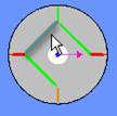
The path lines appear as green lines on the CAD model. The red line indicates the starting hit, and the orange line indicates the ending hit. You can also modify hit locations by simply selecting and dragging the lines with your mouse.
You can also right-click on any path line or hit and use a shortcut menu to perform a variety of functions. See the "Auto Feature Path Lines Shortcut Menu" topic in the "Using Shortcut Keys and Shortcut Menus" chapter for more information.
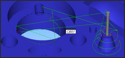
The following example uses an auto circle feature to explain this functionality.
In this example, the starting and ending angles are set to measure only 180 degrees of the circle with four hits.
If you edit the starting or ending angle boxes, the hits display changes as well.
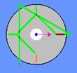
For example, if you change the ending angle from 180 to 360, PC-DMIS would then show the hits around the entire circle.
Alternately, with supported Auto features, you can click on a hit target and drag it to a new location. The software updates the start or end angle in the dialog box accordingly.
You can click on a path line and drag any hit to a new location.
To modify a path line, move the mouse over the path line until PC-DMIS highlights the line, then click and drag the hit to a new location.
Suppose your auto circle uses three sample hits to locate the surface around the circle. PC-DMIS shows these lines as well.
To modify sample hit path lines, click on and drag these lines to a new location.
If you don't have user-defined hits, PC-DMIS dynamically updates the Spacer value as well as the feature hits.
If you already have user-defined hits, PC-DMIS will modify only that one sample hit's location.
Show Path Lines from Previous Auto feature
With the Show Hit Targets icon selected, you can also show temporary path lines from the previous Auto feature to the one you're currently creating. To do this, select the Operation | Graphic Display Window | Clearance Moves | With Feature Creation menu item before you access the Auto Feature dialog box.
Temporary Path Lines between Auto features
Clicking Create from the Auto Feature dialog box when doing this action creates the Auto feature as usual, and it also inserts a preceding MOVE/POINT command into the measurement routine.
To expand this functionality to test for collision detection between the two features, select the Operation | Graphic Display Window | Clearance Moves | With Collision Detection menu item. See "Inserting Clearance Moves with Collision Detection" in the "Inserting Move Commands" chapter.