A newer and simpler Calibrate ScanRDV method discussed in the "Type of Operation area" topic is also available.
When you calibrate a contact-based analog scanning probe, the measured tip size may differ from the nominal tip size. This depends on the type of machine and the type of calibration method selected. On some machine types, this deviation may be calculated and sent to the machine controller separately from the nominal size as a radial deviation. On these machines, this deviation can be sensitive to how the calibration data was collected, particularly in terms of whether discrete hits or scans were used. This can sometimes lead to an apparent size discrepancy during post-calibration measurement. This depends on whether a given feature is measured using discrete hits or scans.
To address this discrepancy, some of these machine controllers (currently those that use the Leitz interface) have been enhanced to support using separate deviations for discrete hit measurement (PRBRDV) and scan measurement (SCNRDV). To support this, you can use the following procedure in PC-DMIS to update the SCNRDV after the regular calibration is complete.
Procedure Overview: To do this, scan a calibration artifact of known size. Typically, you would scan one or more circles around the equator of a calibration sphere or the inside of a ring gage. Construct a circle feature from the scans and then use a "Calibrate Active Tip" command to update the calibration data for the tip.
Calibration Procedure
Do a traditional tip calibration. This calculates the usual parameters such as the tip offset and deflection coefficients and sets both the PRBRDV and SCANRDV to the one resulting deviation. You can do this tip calibration by using a separate, already prepared, calibration measurement routine, or in a preceding portion of the same measurement routine used in step 2, or on the spot interactively by accessing the Probe Utilities dialog box and using the Measure buttons. See "Calibrating Probe Tips".
Create a measurement routine with the following:
One or more scans that measure a calibration artifact of known size. These are typically basic circle scans that measure the equator of a calibration sphere or the inside of a ring gage. The artifact does not have to be something defined as a calibration tool inside PC-DMIS. For details, see "Performing a Circle Basic Scan".
A best fit recompensated (BF Recomp) constructed circle feature that references the desired scans. For details, see "Constructing a Circle Feature" in the "Constructing New Features from Existing Features" chapter in the PC-DMIS Core documentation. Other constructed circle types or non-circle features are not currently supported for SCNRDV calculations.
The theoretical size for the constructed feature must correctly match the size of the calibration artifact. Also, you must specify the theoretical diameter for the measured artifact in the input parameters for the constructed circle. The difference between the theoretical and measured size of the constructed circle is the basis for establishing the SCNRDV value.
A "Calibrate Active Tip" command that references the constructed circle. For details, see "To Automatically Calibrate a Single Tip" in the "Defining Hardware" chapter in the PC-DMIS Core documentation. When you use this command with this type of circle as the input feature, the calibrate single tip command does not require a reference to a calibration sphere.
Execute the measurement routine describe in the previous step. This updates the SCNRDV, based on the difference between the theoretical and the measured size for the constructed circle, while leaving the tip offset and PRBRDV unchanged.
The BF recomp circle and "Calibrate Single Tip" commands described in step 2 must exist in the measurement routine at the time the scans are executed for calibration, because they affect how the scans are executed on the machine.
A Portion of a Sample Calibration Measurement Routine
SCN_FORCAL =BASICSCAN/CIRCLE,NUMBER OF HITS=54,SHOW HITS=NO,SHOWALLPARAMS=NO
ENDSCAN
CIR_PRECAL=FEAT/CIRCLE,CARTESIAN,IN,LEAST_SQR,YES
THEO/<0,0,5>,<1,0,0>,50
ACTL/<-0.0007,-0.0007,-0.0001>,<0,0,1>,49.9967
CONSTR/CIRCLE,BFRE,SCN_FORCAL,,
OUTLIER_REMOVAL/OFF,3
FILTER/OFF,UPR=0
CALIBRATE ACTIVE TIP WITH FEAT_ID=CIR_PRECAL
In the above sample, a single circle scan inside a 50 mm ring gage was performed, the constructed circle feature was created from that, and then the calibrate active tip command was used to update the SCNRDV value for the active tip. If appropriate for the particular measurement to be performed, the constructed circle may have more than one scan as input.
In some cases, a better average value might be obtained by including both a clockwise scan and a counterclockwise scan.
Manually Editing SCNRDV
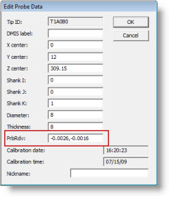
To view or manually edit the SCNRDV, select the desired tip in the Probe Utilities dialog box and click the Edit button. The Edit Probe Data dialog box appears with the PrbRdv box containing both the PRBRDV and SCNRDV values separated by commas, like this:
Renishaw SP25 Scanning Probes
The procedure above is primarily oriented toward traditional analog scanning probes that are initially calibrated using discrete hits. Due to the probe being calibrated with discrete hits, subsequent measurements with discrete hits are generally good. However, further adjustment is sometimes needed to get a SCNRDV that is more suitable for scan-based measurement.
For the Renishaw SP25 scanning probes, the situation is somewhat reversed because the initial (full) calibration is performed using a series of scans. The result of this calibration can sometimes be that the scan measurement is good, but a size discrepancy may then exist when measuring using discrete hits.
To help address this issue, a modification has been made to the "Partial" calibration procedure for the SP25. That partial calibration uses discrete hits and updates the tip offset and size without changing the deflection coefficients produced by the full scan-based calibration. With this modification, when updating the result for size, the partial calibration procedure now updates PRBRDV but does not modify the SCNRDV value.
If a full calibration is performed followed by a partial calibration, the resulting PRBRDV is from the discrete hit-based partial calibration. The SCNRDV is still from the full scan-based calibration.
Although the initial scan-based calibration for an SP25 may make it less likely to be needed; if necessary, this new SCNRDV procedure can be used with an SP25 just like with any other analog scanning probe.