To open the UniScan dialog box, select Insert | Scan | UniScan.
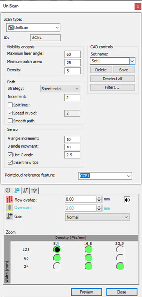
UniScan dialog box
The top portion of the UniScan dialog box contains these areas:
Visibility analysis area
This area defines the parameters of the visibility analysis performed on the selected CAD surfaces.
It is important that you correctly orient the CAD surface vectors. PC-DMIS colors incorrectly oriented surfaces black in the Graphic Display window to alert you that they need to be fixed. For details on how to configure CAD vectors, see the "Editing CAD Vectors" topic in the PC-DMIS Core documentation.
Maximum laser angle box - This value defines the maximum angle the probe tip can have to the normal of each triangle on the CAD surfaces. The default maximum allowed value is 70 degrees. The default minimum value is 10 degrees. You can set these default values in the UniScan section of the Settings Editor with the ConeAngleMaxValue and ConeAngleMinValue entries, respectively. This parameter has a direct impact on the number of tips needed to fully cover the selected surfaces. The smaller the value, the more tips you will need.
Minimum patch area box - Based on the Maximum laser angle value, each laser tip covers a specific area or patch of the selected surfaces. PC-DMIS discards patches with an area smaller than this value.
This can be very useful if you have areas with small details and you don't want to create scans on those areas.
Density box - The selected surfaces are tessellated with a maximum triangle size equal to this value in the measurement routine units. The smaller the Density value, the larger the tessellation and the longer the analysis takes to complete.
CAD controls area
This area provides tools that you can use to help in the selection of the surfaces that the UniScan will cover. You can single-click or box-select the surfaces to select them in the Graphic Display window. You can also define filters that you can apply to the box-selected surfaces.
You can save the selected surfaces for later use. To do this, select the surfaces and then type a name in the Set name box and click the Save button. The software adds the set to the list. You can select different surfaces on the CAD and define other sets and save them the same way. You can switch from one set to another when you select a different set from the list.
To delete a set from the list, select a set name and click the Delete button.
Click the Deselect all button to clear all selected surfaces. The saved sets are still available in the list but no longer applied to the CAD.
Click the Filters button to open the CAD Faces Filter dialog box.
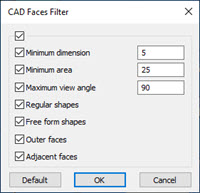
CAD Faces Filter dialog box with All Filters selected
From this dialog box, you can select the filters that you want to apply to the box-selected surfaces.
You must box-select the surfaces for the CAD Faces Filter to take affect. To learn about box-selecting, see "Box-Selecting to Create Multiple Auto Features" in the PC-DMIS Core documentation.
Select the very top All Filters check box to select all the filters. See the descriptions below for each filter type.
Minimum dimension check box and input box - When you select this check box, you can type an entry into the Minimum dimension input box to set a minimum dimension value. This forces PC-DMIS to only select surfaces that have at least this dimension value.
Minimum area check box and input box - When you select this check box, you can type an entry into the Minimum area input box to set a minimum area value. This allows you to select surfaces that have at least this area value.
Maximum view angle check box and input box - When you select this check box, you can type an entry into the Maximum view angle input box. This allows you to box-select all faces in the current CAD view that have an angle smaller or equal to the entered value.
Regular shapes check box - This option forces PC-DMIS to select only regular shapes such as circles, cones, planes, and spheres.
Free form shapes check box - This option forces PC-DMIS to select only freeform-type surfaces.
Outer faces check box - This option forces PC-DMIS to select surfaces that are not internal surfaces such as cylinders and spheres.
Adjacent faces check box - This option selects all faces that share a boundary with the selected face. If there are gaps between adjacent faces that are greater than the fixed accuracy of the CAD, PC-DMIS does not select them.
The Default button selects all but the Adjacent faces option.
Path area
Strategy list - The list provides these possible options:
Sheet metal - Select this option for sheet metal parts which mainly have freeform surfaces.
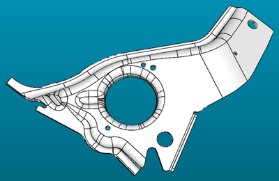
Example of a sheet metal part for UniScan
Prismatic - Select this option for more prismatic-like parts such as the Hexagon block.
Segmented - This option is only available when you have a CMS probe head with a C-joint. This strategy is for parts that have large holes. It sub-divides the patch using the same tip into areas that can be scanned along their longest direction. This reduces the number and length of scans.
Example of a segmented part for UniScan
Increment check box and input box - When you select this check box and type a value, this is the distance between the control points of the generated scan.
Split lines check box and input box - When you select this check box and type a value, scan paths are split when the distance between two consecutive points is larger than this value. This value should reflect the minimum size of the hole that the scan path should skip. When you click on a surface, this field is initialized with the size of the of the largest hole if any.
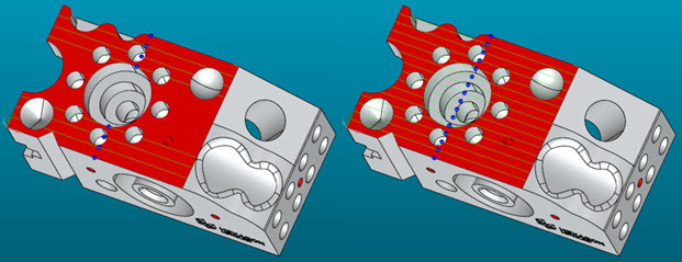
Example with the Split lines option enabled (left) and disabled (right)
Speed in void check box and input box - When you select this check box, you can set a faster scan speed when the software detects that control points are over empty spaces (such as holes).
There are two ways to change this value:
Once you select this check box, click in the Speed in void input box to open the Edit Scan Speed dialog box.
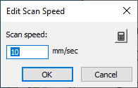
Option 1 is to type a value directly into the Scan speed input box.
Option 2:
Click the Calculate from
stripe spacing button  to open the Calculate Scan Speed dialog
box.
to open the Calculate Scan Speed dialog
box.
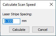
Type a value into the Laser Stripe Spacing input box and click the Calculate button. PC-DMIS calculates the new value and updates the value in the Speed in void input box.
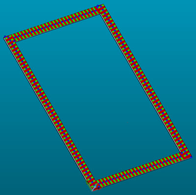
The yellow control points in this image are the control points that PC-DMIS assigns a faster speed to when it performs the UniScan:
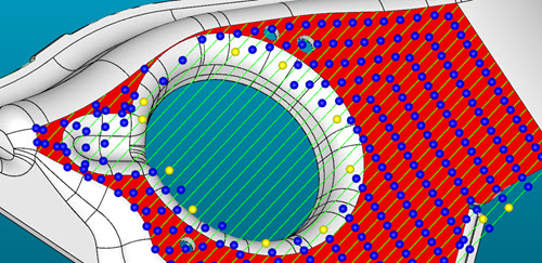
Example of yellow control points which you can apply a faster scan speed to with the Speed in void option
Smooth path check box - When you select this check box, PC-DMIS provides a B-spline path smoothing to the scan.
Sensor area
A angle increment box - Each sensor has its own a pre-defined built-in A angle increment value. The software uses this value to generate all possible tips for use in the visibility analysis. You can change this value, but it cannot be less than the default value of 2.5. The smaller the value, the more tips you can use to perform the scan analysis and the longer the analysis takes.
B angle increment box - This is the same as the A angle increment option, but it applies to the B angle.
The value of these increment options has a direct impact on the speed of the analysis performed. The smaller the increment value, the more tips PC-DMIS uses to perform the visibility analysis and the longer the analysis takes.
The A angle increment and B angle increment options are only available if the Insert new tips check box is selected.
Use C angle check box and input box - This option is only available when the current active laser sensor is mounted on a continuous wrist. The software uses the angle increment value to correct the orientation of the laser when necessary. You must use this option for the Segmented strategy.
Insert new tips check box - When you select this check box, PC-DMIS enables the A angle increment and B angle increment options and only uses the tips defined in the current laser sensor in the analysis.
Miscellaneous
Pointcloud reference feature list - Use this list to select the pointcloud (COP) that you want to use for the scan.
Commands Area
This area is only available if you select the Prismatic strategy. When available, this area provides these options:
Linear - PC-DMIS creates linear open scans when it creates the UniScan group.
Patch - PC-DMIS creates patch scans when it creates the UniScan group.
Probe Toolbox Notes
Laser Scan Properties - PC-DMIS uses the Row Overlap option to define the coverage of the selected scan surfaces.
PC-DMIS considers the Stripe Width, Clipping Region, and Field of View Offset values when performing the visible scan analysis.
You must include the center of the laser trapezoid when setting the clipping regions. As an example:
Set the upper and right values to be greater than or equal to 50
Set the lower and left values to be less than or equal to 50
For details on Probe Toolbox Laser Scan Properties tab, see the "Laser Probe Toolbox: Laser Scan Properties tab" topic in the PC-DMIS Laser documentation.
More: