Step 12: Select Additional Features
Along with taking hits with your probe to measure features,
you can use the QuickFeatures functionality to add features to your measurement
routine. QuickFeatures provide a handy way to add features if you have
a CAD model for the part.
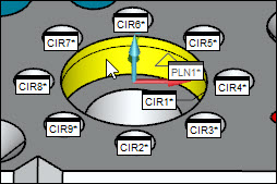
Top Face - Add Bolt Hole Pattern of Eight Circles
(CIR2 - CIR9)
This process adds eight more circle features into the
measurement routine from a bolt-hole pattern.
From the Graphic Modes
toolbar, choose Translate mode ( ).
).
On your graphics model, click the top face
to select it (1). It turns a highlighted, light-blue color.
Hold the Shift key and hover the pointer over
a small circular feature. This tutorial uses the circle that is nearest
to the bottom edge of the top face. This highlights all circular features
of that diameter on that surface (2).
Once all those circle features are highlighted
in yellow, click the feature to create the highlighted circular features
(3).

PC-DMIS inserts all eight circle features
(CIR2 through CIR9) into the Edit window.
- From the measurement strategy widget (if it appears), click the
Apply All button to accept the features:

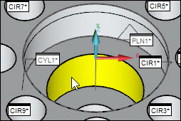
Top Face - Add Two Nested Large Inner Cylinders (CYL1
and CYL2)
This process adds two inner cylinder features nested
within each other into the measurement routine.
Click the top surface again to deselect it.
Hold the Shift key and hover the pointer over
the inside surface of the larger inner cylinder. You may need to zoom
in on the part to select the cylinder:
Once it highlights the cylinder in yellow,
click the cylinder to create the feature. PC-DMIS inserts CYL1 into
the Edit window.
From the measurement strategy widget, click
Apply ( )
to accept the feature.
)
to accept the feature.
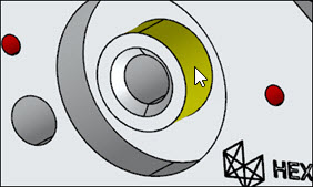
Use QuickFeatures and repeat the above on the
smaller nested inner cylinder:
PC-DMIS inserts CYL2 into
the Edit window.
Front Face - Add the Outer Cylinder (CYL3)
This process adds the outer cylinder features on the
front face into the measurement routine.
Hold the Shift key and hover the pointer over
the outside surface of the outer cylinder on the front face.
Once the pointer highlights the cylinder in
yellow, click the cylinder to create the feature. PC-DMIS inserts
CYL3 into the Edit window.
From the measurement strategy widget, click
Apply ()
to accept the feature.
Front Face - Add an Inner Cylinder (CYL4)
This process adds the inner cylinder features on the
front face into the measurement routine.
On the front face, locate the inner cylinder
that is directly beneath and perpendicular to the central bore on
the top face.
Hold the Shift key and hover the pointer over
the inside surface of the cylinder.
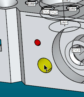
Once the pointer highlights the cylinder in
yellow, click the cylinder to create the feature. PC-DMIS inserts
CYL4 into the Edit window.
From the measurement strategy widget, click
Apply ()
to accept the feature.
For more information on QuickFeatures, see the "Creating
QuickFeatures" topic in the "Creating
Auto Features" chapter in the PC-DMIS Core documentation.
Go
to the next step: "Construct
New Features from Existing Features"
Related
Topics:
Creating
a Measured Circle
Creating
a Measured Cone