
(This item pertains to the Probe Utilities dialog box, accessible through Insert | Hardware Definition | Probe.)
The Add Tool button displays the Add Tool dialog box. To access this button, select the Measure button in the Probe Utilities dialog box (Insert | Hardware Definition | Probe).
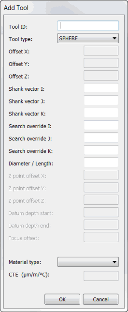
Add Tool dialog box
The Add Tool dialog box allows you to store data that describes the qualification tools. Each tool is assigned a sequential ID number.
Once you define a new tool, PC-DMIS inserts it in the List of available tools list in the Measure Probe dialog box.
You must define at least one probe tip before you can measure a calibration tool.
To add a tool to the List of available tools list, select the Add Tool button to open the Add Tool dialog box.
You can define these items:
Tool ID - In this box, type the name of the tool you are defining.
Tool type - Select the type of calibration tool. Some items are available for selection only if you use a specific probing system.
SPHERE
SPHERE(ARM 2)
POLYHEDRAL
POLYHEDRAL(ARM 2)
RING
RING(ARM 2)
Ring tools are only used with vision probing systems. See the PC-DMIS Vision documentation for information on how to use this tool to calibrate.
Offset X, Y, Z - These X, Y, and Z values define the location of the calibration tool in machine coordinates. To recalibrate a tip, highlight the desired tip in the Active tip list option. Proceed to use the Measure button to calibrate the probe tip. (See "Previewing your Probe Configuration".)
Shank Vector I, J, K - These values define the vector of the shaft on the tool. PC-DMIS uses these values during calibration to avoid the shaft.
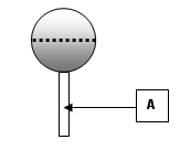
Item A depicts the shaft on a spherical tool
Search Override I, J, K - These boxes define a vector that PC-DMIS uses to determine the most efficient order to measure all the tips. This is enabled when you select the User defined calibration order check box in the Probe Utilities dialog box. For more information, see "User Defined Calibration Order check box".
Diameter / Length - This box displays the diameter or length of a spherical calibration tool.
The Z point offset X, Z point offset Y, Z point offset Z, Datum depth start, Datum depth end, and Focus offset options become enabled only if you are running PC-DMIS Vision. See the PC-DMIS Vision documentation for descriptions of those items.
Material type - This list contains standard material types. When you select a material, its coefficient of thermal expansion (CTE) appears in the CTE box.