A plane can be constructed parallel to any two features. PC-DMIS creates a plane parallel to the first input feature and passing through the centroid of the second input feature.
To construct a parallel plane:
Open the Construct Plane dialog box (Insert | Feature | Constructed | Plane).
From the Method list, select the Parallel option.
From the Feature list, select two features of any type.
From the Display area, select how you want PC-DMIS to display the constructed plane. For details, see the "Using the Display Area" topic in this documentation.
If you want to change the feature theoretical values, select the Feature theoreticals check box and type in the values. For details, see the "Specifying Feature Theoreticals" topic in the PC-DMIS Core documentation.
Click the Create button.
The Edit window command line for this option would read:
CONSTR/PLANE,PLTO,feat_1,feat_2,
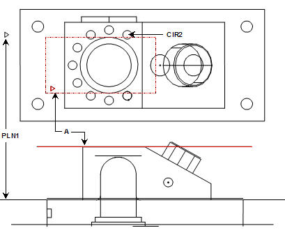
Example 1:
A - Plane constructed parallel to the first feature, a plane (PLN1) and through the second feature, a circle (CIR2)
Constructing a Parallel Plane Using Two Planes
Example 2:
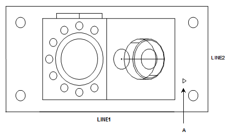
A - Plane constructed through the first feature, a line (LINE1) and parallel to a second line (LINE2)
Constructing a Parallel Plane Using Two Lines