Display area for constructed features
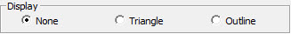
This area defines how the plane feature draws in the Graphic Display window. It contains these options:
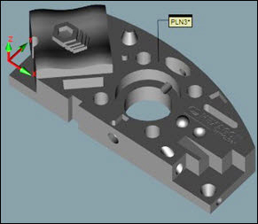
None - PC-DMIS only displays the ID of the constructed plane in the Graphic Display window. It does not display a drawing or outline of the constructed plane.
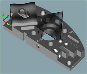
Triangle - PC-DMIS draws the constructed plane as a shaded triangle. The size of the constructed plane depends on the number of hits that make up the plane.
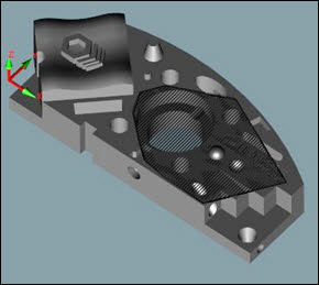
Outline - PC-DMIS draws the constructed plane as an outline from all the hits. The size depends on the number of hits that make up the constructed plane.
The Display Outline of Plane or Do Not Display Plane options on the General tab in the Setup Options dialog box (Edit | Preferences | Setup) define the default display state for future measured or constructed planes. They do not affect the display state of existing planes.