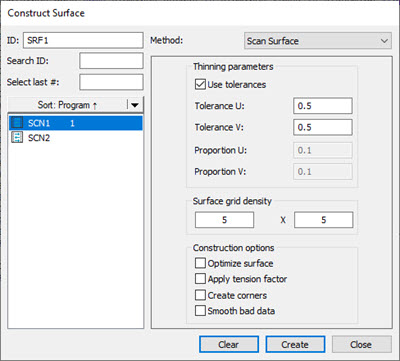
Construct Surface dialog box for Scan Surface method
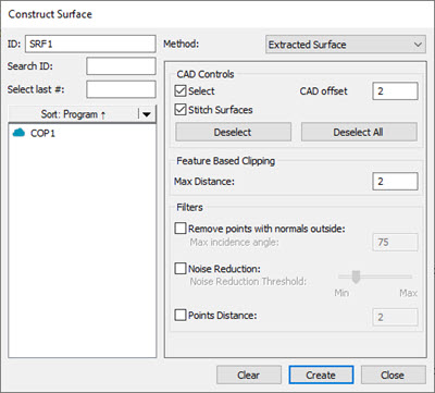
Construct Surface dialog box for Extracted Surface method
There are two types of constructed surfaces available in PC-DMIS: Scan Surface and Extracted Surface.
You typically use the Scan Surface for reverse engineering and can be dependent or independent.
Use the Extracted Surface for reporting surface profile dimensions and is always dependent.
The following table shows the two surfaces, along with their necessary inputs. The only input that the Scan Surface takes is a patch scan. The scan must contain at least two rows of four points per row. The only inputs that an Extracted Surface takes are a COP or Mesh object.
CONSTRUCT FEATURE TYPE |
SYMBOL IN EDIT WINDOW |
OF INPUT SETS |
INPUT #1: |
COMMENTS |
| Scan Surface | DEPENDENT |
1 |
Patch scan containing at least 2 rows with 4 points per row |
The surface will update as the input feature changes. |
INDEPENDENT |
1 |
Patch scan containing at least 2 rows with 4 points per row. |
This uses the input feature for construction only. |
|
Extracted Surface |
CONSTR/SURFACE,EXTRACTED |
1 |
COP or Mesh object |
Constructs an extracted surface from the COP or Mesh object. |
If you select inappropriate feature types, PC-DMIS displays this message on the Status bar:
"Cannot construct [feature]. Combination of input features not accepted."
To construct a Surface:
Access the Construct Surface dialog box (Insert | Feature | Constructed | Surface).
Select the type of constructed surface (Scan Surface or Extracted Surface) from the Method list.
Select the appropriate feature from the Feature list:
For the Scan Surface method, select the patch scan.
For the Extracted Surface method, select the Pointcloud or Mesh.
Select the various construction options. For details on the options available, see the following topics in this section of the PC-DMIS Core documentation.
Click the Create button.
The Edit window command line for a Constructed Surface using the Scan Surface method would read:
feature_name=FEAT/SURFACE,TOG1,CONTROL POINTS U,
             CONTROL POINTS V, NUM POINTS FIT,TOG2
             THINNING PARAMETER U, THINNING PARAMETER V
             CONSTR/SURFACE, INPUT TYPE, INPUT ID
The actual Edit report displays in all capital letters.
DEPENDENT is the default construction type for the Scan Surface method. You can use the TOG1 parameter to switch between Dependent and Independent.
TOG1 = Dependent or Independent.
TOG2 = Tolerance or Proportion
The Edit window command line for a Constructed Surface using the Extracted Surface method would read:
SRF1=FEAT/SURFACE,THEO_THICKNESS=0,MAX DISTANCE=2
     CAD OFFSET=2,REMOVE POINTS WITH NORMALS OUTSIDE=ON,75
     NOISE REDUCTION=ON,20,DISTANCE=ON,2
     CONSTR/SURFACE,EXTRACTED,REF=COP1,SIZE=0
Notice that there is no Dependent or Independent toggle for an Extracted Surface. This is because the Extracted Surface is always dependent – it is always associated with the COP or MESH you use to create it and updates if you change the input.
The following topics describe the available options for constructing a surface:
More:
Constructing a Dependent/Independent Scan Surface