For details on extracting Auto features from a Mesh, see the "Extracting Auto Features from a Mesh" topic in the PC-DMIS Laser documentation.
For details on extracting Auto features from a Pointcloud (COP), see the "Extracting Auto Features from Pointclouds" topic in the PC-DMIS Laser documentation.
A Constructed Extracted Surface is a collection of segregated points related to a surface on the CAD model. It does not create a CAD surface, its intended use is for dimensioning purposes only.
You can construct a surface that is extracted from a scanned Pointcloud (COP) or Mesh.
To do this:
Ensure that your measurement routine contains a Pointcloud (COP) or Mesh command.
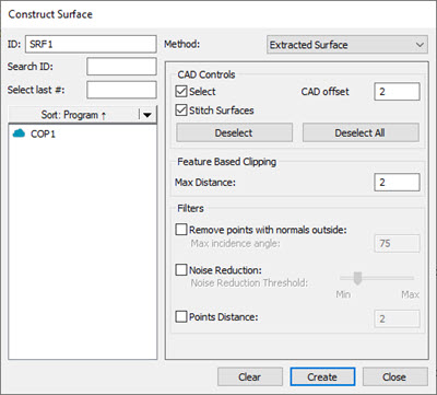
Open the Construct Surface dialog box (Insert | Feature | Constructed | Surface) or from the Constructed Feature toolbar (View | Toolbars | Constructed Features) and select the Extracted Surface option from the Method list.
Construct Surface dialog box for Extracted Surface method
From the Reference area, select the COP or Mesh that you want to use to extract the surface from.
From the CAD Controls area, select the Select check box to select the CAD surface(s) in the Graphic Display window that you want to use to extract the Constructed Surface from.
You can clip data within an offset boundary around all the CAD elements on the selected surface(s) with the CAD offset option in the CAD Controls area. This is also called CAD segregation. For details, see the "CAD offset" section of the "Feature Based Clipping Parameters" topic in the PC-DMIS Laser documentation.
You can stitch surfaces together with the Stitch Surfaces option. If you select multiple contiguous surfaces on the CAD model, the software stitches these surfaces together and processes them as one surface.
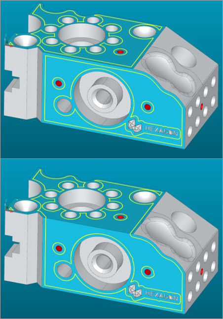
Examples before (top) and after (bottom) applying the Stitching Surfaces option
The advantage of stitching surfaces together is that you would get one continuous pointcloud rather than one with gaps where the surfaces meet if they were processed as individual surfaces.
This is especially evident with the Extracted Surface command. The main aim of the Extracted Surface command is to provide a way for you to report the profile of a surface. Stitching ensures that there is no loss of data where the surfaces meet.
In this example, you can see that without stitching, there are gaps (twice the CAD offset) between each curve:
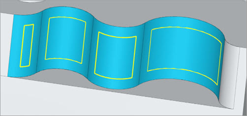
If you want to check the transition between the surfaces of each of the curves on a CAD model, stitching provides a way for you to detect whether there was a smooth transition or a step.
In the Feature Based Clipping area, type the Max Distance value. This is the maximum distance in measurement routine units that a point can be from the CAD model to be considered a valid point.
If you want to filter out any points that are outside of a maximum incidence angle, from the Filters area, select the Remove points with normals outside check box and type the value in the Max incidence angle box.
In the Filters area, if you want to filter out the noise in your data, select the Noise Reduction check box and use the Noise Reduction Threshold slider to set the level of noise reduction you want to apply.
In the Filters area, you can set the minimum distance a point can be from any other point before PC-DMIS discards it. If the distance between a point and any of its neighboring points is less than this value, the point is discarded. To do this, select the Points Distance check box and set a value in the box.
Based on the parameters that you specified in the dialog box, PC-DMIS does an analysis of the candidate points and returns (or extracts) the extracted constructed surface and projects it to the surface.
Click the Create button.
PC-DMIS creates the command for the Extracted Constructed Surface in the Edit window:
SRF1 =FEAT/SURFACE,THEO_THICKNESS=0,MAX DISTANCE=1
     CAD OFFSET=2,STITCH SURFACES=YES,REMOVE POINTS WITH NORMALS
     OUTSIDE=OFF
     NOISE REDUCTION=OFF,DISTANCE=OFF