For details on extracting Auto features from a Mesh, see the "Extracting Auto Features from a Mesh" topic in the PC-DMIS Laser documentation.
For details on extracting Auto features from a Pointcloud (COP), see the "Extracting Auto Features from Pointclouds" topic in the PC-DMIS Laser documentation.
You can construct a square slot that is extracted from a scanned Pointcloud (COP) or Mesh.
To do this:
Ensure that your measurement routine has a Pointcloud (COP) or Mesh command.
Open the Construct Square Slot dialog box (Insert | Feature | Constructed | Square Slot) or from the Constructed Feature toolbar (View | Toolbars | Constructed Features).
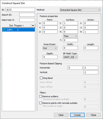
Construct Square Slot dialog box - Extracted Square Slot
From the Method list, select the Extracted Square Slot option.
From the Reference area, select the COP or Mesh that you want to use to extract the square slot from.
Click on the CAD model or data to define the nominal or, in the Point section of the Feature properties area, type the nominal location in the X, Y, and Z boxes.
From the Surface section of the Feature properties area, define the surface vector in the I, J, and K boxes. In the Angle section, enter the corresponding vector angle values. You can use the Material Thickness Type list and the T box below it to type in a material thickness value. For details, see the "Use Thickness" topic in this documentation.
Select whether the extracted square slot is an inner or outer square slot type from the Inner/Outer list.
Enter the width and length of the square slot in the respective boxes. The Width value defines the width of the square slot, and the Length value defines the length or the longest side of the square slot.
Enter the Depth value. This parameter controls the location of the laser focal point in relation to the square slot's outside diameter (outer square slots) or the square slot's center axis (inner square slots). This allows you to control how the laser stripes fall on the square slot's surface by specifying how far or close the laser is to the square slot's surface. A depth of 0 (zero) causes this feature to be calculated at the surface plane height using data found at the lowest possible depth from the surface plane. A depth of any other value causes the software to perform the calculation at that depth.
From the BF Math Type list, select the type of Best Fit algorithm to use to construct the square slot. The available options are:
LEAST_SQR
Least Squares - This calculation type provides
a method of fitting in which the average squared radial distance from
the data points to the square slot is minimized. The square root of this
quantity is the Root Mean Square (RMS) distance. Since the RMS distance
is based on an average, some points may be further than the RMS distance
from the computed square slot.
MAX_INSC
Maximum Inscribed - For
Inner slots, this calculation type generates a slot with the largest
possible footprint that lies within the data. PC-DMIS first computes a
Minimum Circumscribed slot and requires that the center of the Maximum
Inscribed slot lies within it. Do not use this calculation type for arcs
of less than 90 degrees.
MIN_CIRCSC
Minimum Circumscribed - For
Outer slots, this calculation type generates a slot with the smallest
possible footprint that encloses the input data (or input features). This
option could be used when measuring a stud that would fit into a mating
feature. The resulting feature would be the smallest slot into which the
mating feature would fit. Do not use this calculation type for arcs of
less than 180 degrees.
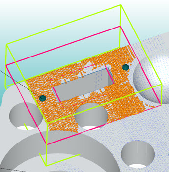
Example of a Constructed Extracted Square Slot showing the candidate points
From the Feature Based Clipping area, define the Horizontal and Vertical values. These values set the dimensions for the green extraction zone region. Consider part variability when you define the extraction zone.
If you want to define the Ring Band offsets, click the Ring Band check box and enter the Inner Offset and Outer Offset values. For details on how the Ring Band works, see the "Ring Band Parameters" topic in the PC-DMIS Laser documentation.
If you want to apply any of the filters in the Filters area, select the available check boxes and enter an appropriate value. For details on the Filters area, see the "Filters" topic in the PC-DMIS Laser documentation.
Click the Create button. Based on the parameters that you specified in the dialog box, PC-DMIS does an analysis of the candidate points and returns (or extracts) the square slot and projects it to the surface. Click the Close button to close the dialog box.
PC-DMIS creates the command in the Edit window:
SLT1=FEAT/SQUARE_SLOT,CARTESIAN,INNER,LEAST_SQR
THEO/<56.303,53.462,0>,<0,0,1>,<1,0,0>,5,15
MEAS/<56.152,53.463,0>,<0,0,1>,<0.999733,-0.0231079,0>,5.123,15.343
DEPTH=50
THEO_THICKNESS,0
HORIZONTAL CLIPPING=7,VERTICAL CLIPPING=9,INNER HORIZONTAL CLIPPING=0
RINGBAND=ON,INNER OFFSET=2,OUTER OFFSET=10
USE OUTLIER REMOVAL=ON,1
REMOVE POINTS WITH NORMALS OUTSIDE=ON,0.5
CONSTR/SLOT,SQUARE,EXTRACTED,COP1
More: