A plane can be constructed a specified distance from the input feature or features.
To construct an offset plane:
Open the Construct Plane dialog box (Insert | Feature | Constructed | Plane).
From the Method list, select the Offset option.
From the Feature list, select a single plane feature or at least three features of any type.
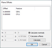
Click the Offsets button to open the Plane Offsets dialog box.
Plane Offsets dialog box
Click the Calculate Noms option and enter the offset values for the input feature or features in the offset field, or click the Calculate Offsets option and change the nominal values (see the procedures below).
Click Calculate to calculate either the nominal values or the offset values.
Click the OK button to close the Plane Offsets dialog box.
From the Display area, select how you want PC-DMIS to display the constructed plane. For details, see the "Using the Display Area" topic in this documentation.
If you want to change the feature theoretical values, select the Feature theoreticals check box and type in the values. For details, see the "Specifying Feature Theoreticals" topic in the PC-DMIS Core documentation.
Click the Create button. PC-DMIS creates the offset plane based on the input feature or features.
Using a Single Plane Input Feature
PC-DMIS creates a parallel plane at the offset distance.
The Edit window command line for this option would read:
CONSTR/PLANE,OFFSET
ID=id1,,, …
OFFSET=val1…
Using Three Input Features
PC-DMIS iterates and constructs a plane such that the shortest distance from each input feature to the plane is the corresponding offset amount. PC-DMIS applies negative offsets in the same general direction that the points are measured. Positive offset values are applied opposite the probing direction. If there is no probing direction (for example, the input points were constructed), PC-DMIS uses the current workplane to determine the general direction for applying the offsets. Positive offsets are applied in the plus direction of the third axis of the current workplane. Negative offsets are applied in the minus direction of the third axis of the current workplane.
The sign (positive or negative) of the offset value controls on which side of the input features the plane is constructed. If you get the opposite plane than was expected, cancel the feature and reconstruct it, reversing the sign of the keyed in offsets. For example, if the offsets are 1.0, 2.5, 3.5, change them to -1.0, -2.5, -3.5.
The Edit window command line for this option would read:
CONSTR/PLANE,OFFSET
ID=id1, id2, id3, …
OFFSET=val1, val2, val3, …
More:
Changing Offsets Directly to Calculate Nominals
Example of Calculating Nominals