The [Basic Scan] tab in the BASICSCAN dialog box (Insert | Scan | Circle, Cylinder, Axis, Center, or Line) is the main tab for each basic scan feature. It is one of these tabs:
CIRCLE
CYLINDER
AXIS
CENTER
LINE
The options on this tab include the following.
#, X, Y, and Z Columns
# - Displays the points used to generate the scan. These include the following:
Start Point: Used with axis, center, and line scans. This point is the start point from which the execution starts.
End Point: Used with axis, center, and line scans. This point is the end point at which the execution ends.
D: Used with a line scan. The Direction Point starts the scan and calculates the cut plane. The probe always remains within the cut plane while doing the scan.
Centroid: Used with circle and cylinder scans. This point (found in the first list in the # column) is the center of the circle or cylinder. You can type the center directly or get it from the machine or CAD. For a cylinder, this is the center from which the execution starts.
X, Y, and Z - These columns display the coordinates for the item in the # column.
Vector, I, J, and K Columns
Vector - Displays the type of vector. These include the following:
InitVec: Used with all of the basic scans. The InitVec is the surface normal vector of the point the scan defines as 0 degrees for the circle and cylinder scan types. It is the surface vector of the starting point for the other scan types.
CutVec: Used with circle, cylinder, center, and line scans. The CutVec defines the plane in which the feature lies.
EndVec: Used with the line scan. The end vector is the approach vector at the end point of the scan.
DirVec: Used with the line scan. The direction vector is the vector from the start point to the direction point.
I, J, and K - These columns display the IJK vector information for the vector.
Surface Thickness Box
This is used with all basic scans. Use the Surface thickness box to enter the part thickness. PC-DMIS applies this material thickness automatically when it uses CAD surface data. This thickness is applied along the surface normal vector when FINDNOMS mode is selected. PC-DMIS pierces the CAD surfaces to get the nominals.
Control Points Button
This is used with the line scan. This button displays the Control Points dialog box. This dialog box contains controls that are similar to the Control Points tab in the scan dialog box. For more information, see "Control Points Tab".
This button appears only if you are using a continuous contact probe (analog probe), such as the SP600. You can select it once you define the Start, Direction, and End Points of the line scan.
Type List
The Type list defines the type of circle, cylinder, or center scan to perform. When you use it with circle and cylinder scans, this switches between:
IN: Defines the scan as a hole.
OUT: Defines the scan as a stud.
PLANE: A plane circle is executed on the plane the circle is lying on.
When you use this option with center scans, it switches between the available centering methods:
Axis: The Start Point (S) is projected on the defined Axis (A). The resulting point is (SP). The InitVec is projected in the plane defined by the Projected point (SP) and the axial direction (A). The direction (N) thus defined is vertical to the axial direction. Thereafter, as centering is performed, the probe’s center point remains in the plane defined by the axial direction and (SP). Centering takes with/against the direction (N) as an input, and the probe tip is free in the direction defined by the axial direction (A) crossing the direction (N).
S = Start Point
A = Defined Axis / Axial direction
SP = Projected Start Point
N = Direction vertical to the axial direction
Plane: After probing the point defined by the Start Point, the CMM centers with/against the probe direction while remaining free in the plane defined by the CutVec.
Diameter Box
This is the diameter value for Circle and Cylinder feature scans.
Conical Check Box
This check box enables you to perform circle scans more quickly when not perpendicular to the part surface. PC-DMIS continues to monitor the probe force as needed.
Start Angle Box
This box defines the start angle (in degrees to scan) from the start point for circle scans. You can use both positive and negative angles.
PC-DMIS considers positive angles as counterclockwise.
PC-DMIS considers negative angles as clockwise.
PC-DMIS considers the CutVec as the axis about which the angle rotates.
End Angle Box
This value is the same as the Start angle box except that it defines the end angle for circle scans. With start and end angles, you can define a specific portion of a hole or stud to scan.
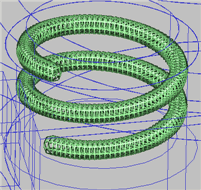
Angle Box
When you perform cylinder scans, this value defines how far around the cylinder to scan. For example, if you type 360, it scans one complete revolution. If you type 720, it scans two revolutions, and so forth.
Depth Box
This value is the depth applied against the CutVec direction for circle and cylinder scans. You can use both positive and negative values.
Pitch Box
This box defines the distance between threads along
the axis of the feature when you perform cylinder scans. This enables
your scan to move in a spiral-like fashion along the cylinder.